This chapter describes how to use the L1 and L2 controllers to monitor and manage an SGI Altix system in the following sections:
“Operating the L1 Controller on Altix 450 and Altix 4700 Systems”
-

Note: Most, but not all, of the L1 controller commands can be used with all systems. You may also find that some specific examples using L1 controller commands in this chapter may show components not applicable to your system, but this does not indicate that these commands cannot be used to monitor and manage your system.
The LCD on the front of certain enclosures can be used to provide limited control and monitoring capabilities. The LCD provides the functionality to power up, power down, and reset the system. See the appropriate SGI hardware manual for your system for a detailed description of the LCD.
A serial or network connection to the system controller network allows you to control and monitor your system using a command line interface. Additionally, this connection also accesses the system console, providing an interface to boot your system.
| Note: See “Upgrading System Controller Firmware” for instructions to upgrade your L1 controller firmware and L2 controller firmware. |
See Chapter 3, “L1 and L2 Controller Commands” for a list of L1 and L2 controller commands you can use to monitor and manage the various devices.
The L2 controller operates in one of the following three modes, each of which is discussed in the sections that follow. For information on operating the L2 controller on the new SGI Altix 4700 system, see “Operating the L2 Controller on Altix 450 and 4700 Systems”.
The L2 prompt is visible and all input is directed to the L2 command processor (see “L2 Mode”)
Output from the system is visible and all input is directed to the system (“Console Selection”).
The prompt from a single L1 is visible, and all input is directed to that L1 command processor (see “L1 Mode from L2”.)
After a connection to the L2 controller, a variation of the following prompt appears, indicating that the L2 is ready to accept commands:
L2> |
When a system is partitioned, the L2 supports targeting a command to a single partition. To set the destination to a single partition preceed the targeting information with the “partition <number>”, such as partition 1. This sets the default destination to all bricks in partition 1.
Another option is to the use L2 controller select partition <number> command, such as the following:
L2> select partition 1 |
This sets the default destination to all the bricks in partition 1 and also selects the correct system console for partition 1, used when the L2 controller is put in system console mode.
The L2 controller provides a fail-safe mechanism for certain commands that could produce undesirable results when you try to apply certain commands to a partition.
Command Interpretation
Some L2 commands are the same as the L1 commands. In many cases, this is intentional because the L2 provides sequencing that is necessary for a command to function correctly.
When L1 and L2 commands are similar, you can assure that an L1 command is entered for the bricks in the current destination by preceding <L1 command> with the L1 command (this is a one-time destination), as follows:
L2> r 2-4,7 l1 <L1 command> |
The following are common subchannels associated with console communications on an SGI Altix system:
Subchannel 0A specifies node|blade 0, CPU A.
Subchannel 0C specifies node|blade 0, CPU C.
Subchannel 1A* specifies node|blade 1, CPU A.
Subchannel 1C specifies node|blade 1, CPU C.
Subchannel 2A specifies node|blade 2, CPU A.
Subchannel 2C specifies node|blade 2, CPU C.
Subchannel 3A specifies node|blade 3, CPU A.
Subchannel 3C specifies node|blade 3, CPU B.
node|blade 0 console subchannel.
node|blade 1 console subchannel.
node|blade 2 console subchannel
node|blade 3 console subchannel
On blade-based systems, the numeric part of the console descriptor refers to the blade slot, on non-blade based systems, it refers to the node. (There is only one node on a compute blade which is node 0.) The alphabetic portion refers to the CPU index which can be A, B, C, or D or “console” which identifies the appropriate CPU to receive console input.
[1]
To select a subchannel as the current subchannel, for a specific node/blade and CPU, perform the following:
L2> select sub 0a |
or
L2> select sub 0c |
or
L2> select sub 2a |
and so on.
| Note: Under normal conditions, it is not necessary to manually select a system console beyond selecting a partition on a partitioned system. The following instructions would be required in a debugging environment. To restore the console to the default value, use the select reset command. |
For console subchannels, perform the following:
L2> select sub console0 |
or
L2> select sub console1 |
and so on.
The output console input: 001c05 console0 shows that the L2 will send console input to brick 001c05 and the subchannel to be used is the console0 subchannel.
To change system console status from one brick to the attached C-brick, use the select <rack> <slot> command:
001c05-L2> select r 2 s 1 console input: 001c05 console1 console output: not filtered. 001c05-L2> |
When selecting the rack and slot for the console, you could also select <rack>.<slot>, as follows:
001c05-L2> select 2.4 |
To change the subchannel used on the selected brick, use the select command followed by the subchannel number or the word console:
001c05-L2> select sub 0A console input: 001c05 CPU 0A console output: not filtered. 001c05-L2> |
In L1 mode, the prompt from a single L1 is visible, and all input is directed to that L1 command processor.
To enter L1 mode, type the l1 command and specify a rack and a slot, as follows:
L2> r 2 s 1 l1 entering L1 mode 002c01, <CTRL-T> to escape to L2 002c01-L1> |
A shorter command line version is, as follows:
L2> 2.1l1 entering L1 mode 002c01, <CTRL-T> to escape to L2 002c01-L1> |
To return to L2 mode, press Ctrl+T, as follows:
002c01-L1> Ctrl+T escaping to L2 system controller, <CTRL-T> to send escape to L1 L2> |
At this point, you can enter any L2 command. When the command completes execution, the L2 returns to L1 mode, as follows:
002c01-L1> |
To permanently engage the L2 mode, press Ctrl+T and type the l2 command, as follows:
002c01-L1> Ctrl+T escaping to L2 system controller, <CTRL-T> to send escape to L1 L2> l2 L2 command processor engaged, <CTRL-T> for console mode. L2> |
The system controller in an Altix 450 or Altix 4700 system can provide L2 functionality.
An Ethernet cable can be plugged into the RJ45 connector on the IRU enclosure or on the Dense router. Connecting the IRU or Dense router to an active LAN via the L2 host connector will cause the system controller to spawn an L2. This connection provides network access to the system controller through the L2. For information on setting up system control on an SGI Alitx 4700 system, see “System Controller Network” in chapter 1, “Operation Procedures” in the SGI Altix 4700 System User's Guide.
| Caution: The L2 network connection must be kept on a private and physically secure network connection. The System Controller does not provide software security, authentication, or safeguards against malicious or careless users. The consequences of unauthorized access to the System Controllers is potential system unavailability, system reconfiguration, and detailed access to every aspect of the system. The recommended configuration for the L2 network connection is a separate, private and physically secure network attachment to an equally separate and physically secure PC. The Linux system hosting the L3 software must be administered to prevent unauthorized access. |
This section describes L2 operation on SGI Altix 4700 systems and covers these topics:
“Configuring an L2's IP Address on an Altix 450 or Altix 4700 System”
“Viewing System Configuration on Altix 450 or Altix 4700 System”
“Setting Command Targeting on Altix 450 or Altix 4700 System”
“Viewing Information, Warnings, and Error Messages on Altix 450 or Altix 4700 Systems”
“Powering On, Powering Off, and Resetting the System From the L2”
“Console Mode from the L2 on Altix 450 or Altix 4700 Systems”
This section refers to setting the IP address on the individual rack unit (IRU) enclosure when using an Ethernet connection.
Setting the IP address of the L2 on the target IRUs should be done before connecting the IRUs to the network as follows:
Connect a serial cable to the serial console port on the target IRU and get the Linux shell prompt.
To see if the L2 is running (it will be if the LAN cable is plugged in and the cable is connected to an active LAN).
At the # prompt type:
# l1cmd l2 L2 Controller is running. # |
If the L2 is not running type:
# init 4 |
This switches the system controller to run level 4 and forces the L2 to be started whether or not the LAN is plugged in.
Verify the L2 is running again as above.
To set the IP address on the L2 type:
#l1cmd l2 ip a.b.c.d 255.255.255.0 a.b.c.255 |
To set the L2 controllers gateway, perform the following command:
#l1cmd l2 IP gw e.f.g.h |
Verifying that the system serial number is set on the L2:
#l1cmd l2 serial |
To set the L2 system serial number:
#l1cmd001c01-L1> l2 serial set <serial number> |
Verifying that msys is enabled (this allows multiple L2s in a system to exist peacefully with other L2s from another system on the same subnet)
#l1cmd l2 multisys |
If msys is off, turn it on:
#l1cmd l2 multisys on |
Reboot the system controller to make the IP address change take effect.
#reboot |
Once this is done for all target IRUs and/or Dense routers (sometimes called the Quad Dense Router (QDR) ) as specified in the system configuration guide, connect them to the network (using an optional Ethernet switch if necessary). For descriptions of individual rack units (IRUs) and Dense routers on an Altix 4700 system, see SGI Altix 4700 System User's Guide.
The L1 rack ID is rack x 100 + slot (rack times 100 plus slot). An example L2 rackid is 5 * 100 + 41 or 541.
Once the L2 is running, you can telnet to the L2, or use an optional SGIconsole.
After the connection to the L2 controller is established, the following prompt appears, indicating that the L2 is ready to accept commands:
olympic-101-L2> |
Common operations are discussed in the subsections that follow.
You can use the L2's config command to view the your system configuration from an IRU level:
olympic-101-L2> config L2 127.0.0.1: - 001 (LOCAL) L1 127.0.0.1:0:0 - 001c31 L1 127.0.0.1:0:1 - 001c21 L1 127.0.0.1:0:2 - 001c11 L1 127.0.0.1:0:3 - 001c01 L2> |
As shown above, config produces a list of IRUs and their locations in the system and the system controller address of each IRU and Dense router. This is similar to the output from using the config command on the L1 with the addition of the L2 IP address, L1 connection, and L1 index. The structure of the IRU and Dense router address is as follows:
a.b.c.d:x:y |
where:
| a.b.c.d | is the IP address of the L2. (In the example above, the IP address is 127.0.0.1.) | |
| x | connection number is only 0 for Altix 4700 | |
| y | is the L1 index |
rrrbss.p
where:
| rrr | is the rack number. | |
| b | is the enclosure type. | |
| ss | is the slot location of the enclosure. | |
| p | is the partition of the enclosure (not present if the system is not partitioned). |
In the example shown above, 001c01 is an IRU in rack 001 and slot position 01.
If a command is not understood by the L2 system controller, in general it is passed to the L1 system controllers. The destination determines which L1s receive the command. A destination, specified by the following, is a range of racks and slots:
rack <rack list> slot <slot list> |
The <rack list> specifies a list of racks. This can be a list delimited by commas, such that 2,4,7 specifies racks 2, 4, and 7. You can use a dash to specify a range of racks, such that 2-4 specifies racks 2, 3, and 4. Both nomenclatures can be combined, such that 2-4,7 specifies racks 2, 3, 4, and 7.
You can specify the <slot list> using the same nomenclature. The slot number, sometimes referred to as a bay number, is the unit position number located on the rack, slightly above where the bottom of the IRU sits. Each rack unit position number is located toward the top of the two lines that mark the unit position that the number represents. For example, the rack numbering for a IRU located in slot 10 would appear on the left front side of the rack.
The slot <slot list> is optional; if not given, then all slots in the specified rack(s) are implied. You should avoid specifying a rack list and a slot list that includes multiple racks and slots, such as rack 2-4,7 slot 1-8,11,13. Generally, you specify a rack and slot together to specify an individual IRU or Dense router.
You can use the aliases r and s to specify rack and slot, respectively. You can use the alias all or * in both the <rack list> and the <slot list>, or by themselves, to specify all racks and all slots.
To send a command to all IRUs in a partition, enter the following:
partition <partition> <cmd> |
Individual IRU and Dense routers can also be targeted with a short <rack>.<slot> prefix. As in 1.11 <command>.
To target individual blades in an IRU use the following syntax:
olympic-101-L2> 1.11 b1 power down |
Executing the above command will power down the blade in blade slot 1 of the IRU in rack 001 U position 11.
Default Destination
When the L2 starts, the default destination is set to all racks and all slots. You can determine the default destination by using the destination command:
L2> destination all racks, all slots L2> |
The following command sets the destinations to rack 2 and 3, all slots:
L2> r 2,3 destination 2 default destination(s) set L2> |
The following example shows what IRUs are found in the default destination. If you enter a command not understood by the L2, the command is sent to these IRUs.
| Note: If you add an IRU to either rack 2 or 3, it is not automatically included in the default destination. You would need to reset the default destination. |
L2> destination 001c01 (127.0.0.1:0:2) 001c01 (127.0.0.1:0:0) L2> |
The following command resets the default destination to all racks and all slots:
L2> destination reset default destination reset to all racks and slots L2> |
Current Destination
The current destination is a range of racks and slots for a given command. For example, the following command sends the command <L1 command> to all IRUs in racks 2, 3, 4, and 7:
L2> r 2-4,7 <L1 command> |
This is a one-time destination.
Command Interpretation
Some L2 commands are the same as the L1 commands. In many cases, this is intentional because the L2 provides sequencing that is necessary for a command to function correctly.
When L1 and L2 commands are similar, you can ensure that an L1 command is entered for the IRUs current destination by preceding the command <L1 command> with the l1 command:
L2> r 2-4,7 l1 <L1 command> |
This is a one-time destination.
All information, warnings, and error messages generated by any of the system controllers are in the following form:
001c01 ERROR: invalid arguments for `ver' command, try “help ver” |
The general format includes an IRU identification and the type of message, followed by the message. A message may be the result of an invalid command, as shown in the example, or the result of tasks running on the L1, such as the environmental monitor.
Each L1 has a log of local events. Use the L1 command log to view events on any of the L1s.
You can power on and power off the system with the power command. This command is interpreted by the L2, because the IRUs must be powered on in a specific order.
L2> power up L2> |
The power command may require several seconds to several minutes to complete. In the example above, all racks and slots in the default destination are affected. Any errors or warnings are reported as described above in TBD. To power on or power off a specific IRU, specify a current destination:
L2> r 2 s 5 power up L2> |
To power on or power off all IRUs in a partition, enter the following:
L2> partition <partition number> <power up or power down> |
To reset the system, enter the following:
L2> reset L2> |
This command restarts the system by resetting all registers to their default settings and rebooting the system controllers. Resetting a running system will cause the operating system to reboot and all data in memory will be lost.
In console mode, all output from the system is visible and all input is directed to the system.
To enter console mode from L2, press Ctrl+D at the L2 prompt and observe the response:
L2> Ctrl+D entering system console mode (001c01 console0), <CTRL_T> to escape to L2 . <system output appears here> . |
To return to L2 mode from console mode, press Ctrl+T:
Ctrl+T escaping to L2 system controller L2> |
At this point, you can enter any L2 or L1 command. When the command completes, the L2 returns to console mode:
Re-entering system console mode (001c01 console0), <CTRL_T> to escape to L2 |
To permanently engage the L2 mode, press Ctrl+T and then enter the l2 command:
Ctrl+T escaping to L2 system controller L2> l2 L2 command processor engaged, <CTRL_D> for console mode. L2> |
When in console mode, the L2 communicates with the IRU set with the select command to be the system console or global master. All input from the console is directed to that IRU. You can set and view the system console with the select command.
The L2 chooses an IRU as the default console in the following order of priority:
The IRU in the lowest numbered rack and slot, which has previously produced console output.
The IRU in the lowest numbered rack and slot.
The select command by itself shows the current console mode settings:
L2> select known system consoles (non-partitioned) 001c01-L2 detected current system console console input: 001c01 CPU 0A console output: not filtered |
The following are ten common subchannels associated with console communications:
Subchannel 0A specifies Blade 0, CPU A.
Subchannel 0C specifies Blade 0 CPU C.
Subchannel 1A specifies Blade 1, CPU A.
Subchannel 1C specifies Blade 1, CPU C.
Subchannel 2A specifies Blade 2, CPU A.
Subchannel 2C specifies Blade 2, CPU C.
Subchannel 3A specifies Blade 3, CPU A.
Subchannel 3C specifies Blade 3, CPU C.
Subchannel console0 Blade 0 console subchannel.
Subchannel console1 Blade 1 console subchannel.
The select command output: “console input: 001c01 console0” shows that the L2 will send console input to IRU 001c01 blade 0 and the console subchannel will be used.
To change the IRU that will be the system console, use the select <rack>.<slot> command, where <rack> is the rack and <slot> is the slot where the IRU is located:
L2> select 1.1 console input: 001c01 console console output: no filtered console detection: L2 detected |
To change the subchannel used on the selected IRU, use the select subchannel <0A|0C|1A|1C> command. (Use the select subchannel console to select the current console as the subchannel of the IRU to be the system console.) For example, to select blade 1, CPU A as the subchannel of the IRU to be the system console, enter the following:
L2> select subchannel 1A console input: 001c01 console CPU1A console output: not filtered |
During the boot process on a system with multiple CPUs, there is a window of time in which the CPUs are all producing output. This can result in a somewhat jumbled output from the L2. However, you can filter console output so that the L2 will show output from only the IRU chosen to receive console input. You can turn on filtering with the select filter on command and turn off filtering with the select filter off command.
If you attempt to communicate with an IRU chosen to receive console input but that is not responding, a time-out condition results:
L2> Ctrl+D entering console mode 001c01 CPU1A, <CTRL_T> to escape to L2 no response from 001c01 Junk bus CPU1A system not responding no response from 001c01 Junk bus CPU1A system not responding |
When this time-out condition occurs, either the IRU is hung or the subchannel is not correct.
In L1 mode, the prompt from a single L1 is visible, and all input is directed to that L1 command processor.
To enter L1 mode, enter the rack and a slot followed by l1:
L2> r 2 s 1 l1 |
An alternate method is:
L2> 2.1 l1 entering L1 mode 001c01, <CTRL-T> to escape to L2 001c01-L1> |
To return to L2 mode, press Ctrl+T:
001c01-L1> Ctrl+T escaping to L2 system controller, <CTRL-T> to send escape to L1 L2> |
At this point, you can enter any L2 command. Once the command is executed, the L2 returns to L1 mode:
re-entering L1 mode 001c01, <CTRL-T> to escape to L2 001c01-L1> |
To permanently engage the L2 mode, press Ctrl+T and enter the l2 command:
001c01-L1> Ctrl+T escaping to L2 system controller, <CTRL-T> to send escape to L1 L2> l2 L2 command processor engaged, <CTRL-T> for console mode. |
L2>
This section describes the L1 controller on SGI Altix 3000 series systems.
The L1 controller operates in one of the following two modes, each of which is discussed in the sections that follow:
L1 mode. The L1 prompt is visible and all input is directed to the L1 command processor.
Console mode from L1 mode. Output from the system is visible and all input is directed to the system.
Note: The console mode from L1 mode is not supported if the system contains an L2 controller.
For information on operating the L1 controller on an SGI Altix 450 and Altix 4700 systems, see .
The brick with which the L1 communicates in console mode is the system console or global master, and you can view and set it with the select command. By default, the C-brick attempts to communicate with its local CPUs when console mode is entered. If the system has been powered on and either one of the bricks received a request to be the system console, then the C-brick attempts to communicate with that brick.
When you see a prompt of the following form, the L1 is ready to accept commands.
001c19-L1> |
Common operations include the following and are discussed in the sections that follow:
An L1 has limited knowledge of the system configuration. A C–brick only has information about its attached I/O brick and, if another C–brick is attached to it, information about that C–brick and its attached I/O brick. An I/O brick only has information about its attached C–brick. An R–brick only has information about itself.
You can view a brick's configuration information with the config command, as follows:
003c01-L1> config :0 - 003c01 :1 - 004i01 :2 - 002c01 :3 - 001x01 003c01-L1> |
Bricks are referenced by their racks and slot or bay locations. These values are stored in nonvolatile memory on the L1. Virtually all system controller communications require that each brick has a valid and unique rack and slot.
If a brick is not set with its rack and slot number, it appears in the output of an L2 config command, as shown in the following example:
L2> config 137.38.88.82.1.0 ---c-- (no rack/slot set) L2> |
To set the rack and slot for a brick, address it by its IP address, USB port, and L1 controller index. Note the following example:
L2> 137.38.88.82:1:0 brick rack 1 L2> 137.38.88.82:1:0 brick slot 8 L2> 137.38.88.82:1:0 reboot_l1 INFO: closed USB /dev/sgil1_0 INFO: opened USB /dev/sgil1_0 L2>config 137.38.88.82:1:0 001c08 L2. |
The following example shows how to set rack 1, slot 8, for the C-brick with an IP address of 127.0.0.1:
L2> config 127.0.0.1: 127.0.0.1:0:0 - ---c-- 127.0.0.1:0:1 - 001i01 127.0.0.1:0:5 - 001c05 L2> :0:0 brick rack 1 brick rack set to 001. L2> :0:0 brick slot 8 brick slot set to 08. L2> :0:0 reboot_l1 INFO: closed USB /dev/sgil1_0 INFO: opened USB /dev/sgil1_0 L2> L2> config 127.0.0.1: 127.0.0.1:0:0 - 001c05 127.0.0.1:0:1 - 001i01 127.0.0.1:0:5 - 001c08 L2> |
To set the rack and slot from the L1 prompt, simply use the brick rack and brick slot commands. To set the rack and slot on one of the attached bricks (an attached I/O brick, C-brick, or a C-brick's I/O brick), use the L1 targeting commands iia, iib or nia, nib, as follows:
001c05-L1> config :0 - 001c05 :1 - ---i-- :5 - 001c08 :6 - 001p01 001c05-L1> iia brick rack 4 ---i--: brick rack set to 004. 001c05-l1> iia brick slot 1 ---i-- brick slot set to 01 001c05-l1> iia reboot_l1 001c05 ERROR: no response from ---i-- 001c05-L1> config :0 - 001c05 :1 - 004i01 :5 - 001c08 :6 - 001p01 001c05-L1> |
In the preceding code, the number after the colon symbol (:) indicates the following:
0 = local brick 1 = IIA (II0) 2 = IIB (II1) 5 = NIA (Nl0) 10 = NIB (N11) |
Only 0 has a valid meaning, other values are arbitrary based on the system type.
To obtain a detailed configuration explanation from the L1 perspective, enter the following:
001c05-L1> config verbose |
All commands affect only the local brick, unless the command is prefixed with an asterisk (*). To target a command to all bricks (including the local brick), prefix the command, as shown in the following example:
003c01-L1> * version 003c01: L1 0.7.37 (Image A), Built 05/24/2001 14:59:42 [P1 support] 004i01: L1 0.7.37 (Image A), Built 05/24/2001 14:59:42 [P1 support] 002c01: L1 0.7.37 (Image A), Built 05/24/2001 14:59:42 [P1 support] 001x01: L1 0.7.37 (Image A), Built 05/24/2001 14:59:42 [P1 support] 003c01-L1> |
The L1 also supports a L1> <rack>.<slot> <command> target. For example,
003c01-L1> 4.1 version 004i01: L1 0.7.37 (Image A), Built 05/24/2001 14:59:42 [P1 support] 003c01-L1> |
You can also target commands to a single attached brick with either the iia, iib, or nia, nib command, as follows:
003c01-L1> iia version 004i01: L1 0.7.37 (Image A), Built 05/24/2001 14:59:42 [P1 support] 003c01-L1> |
All information, warnings, and error messages generated by any of the system controllers are in the following form:
002c01 ERROR: invalid arguments for `ver' command, try “help ver” |
The general format of the message includes a brick identification (this is not present if the command was to the local brick only), type of message, and the message. These messages can be the result of an invalid command (as shown in the example) or from tasks running on the L1, such as the environmental monitor.
Each L1 has a log of local events. Use the L1 command log to view the event on any of the L1s.
You can power on and power off the brick with the power command, as follows:
003c01-L1> power up 003c01-L1> |
If an L2 is not present, you need to power on, power off, and reset the system from one of the C–bricks. You do so by targeting all bricks, as follows:
003c01-L1> * power up 003c01-L1> |
This command can require from several seconds to several minutes to complete.
You can enter the power off and reset commands in similar ways.
In console mode, output from the system is visible and all input is directed to the system.
To enter console mode, press Ctrl+D at the L1 prompt, as follows:
003c01-L1> Ctrl+D entering console mode 003c01 console, <CTRL-T> to escape to L1 . <system output appears here> . |
To return to L1 mode, press Ctrl+T, as follows:
Ctrl+T escaping to L1 system controller 003c01-L1> |
At this point, you can enter any L1 command. When the command completes execution, the L1 returns to console mode, as follows:
re-entering console mode 003c01 console, <CTRL-T> to escape to L1 |
To permanently engage the L1 mode, press Ctrl+T and then type the l1 command, as follows:
Ctrl+T escaping to L1 system controller 003c01-L1> l1 L1 command processor engaged, <CTRL-D> for console mode. 003c01-L1> |
The brick with which the L1 communicates in console mode is the system console or global master, and you can view and set it with the select command. By default, the C–brick attempts to communicate with its local CPUs when it enters console mode. If the system has been powered on and either one of the bricks has a request to be the system console, then the C–brick attempts to communicate with that brick. Enter the select command alone to show the current console mode settings, as follows:
003c01-L1> select console input: 003c01 console console output: not filtered. |
The following are common subchannels associated with console communications on an SGI Altix system:
Subchannel 0A specifies Node 0, CPU A.
Subchannel 0C specifies Node 0, CPU B.
Subchannel 1A specifies Node 1, CPU A.
Subchannel 1C specifies Node 1, CPU B.
Subchannel 2A specifies Node 2, CPU A.
Subchannel 2C specifies Node 2, CPU B.
Subchannel 3A specifies Node 3, CPU A.
Subchannel 3C specifies Node 3, CPU B.
Node 0 console subchannel.
Node 1 console subchannel.
Node 2 console subchannel
Node 3 console subchannel
Each IRU and Dense router in the SGI Altix 450 or Alitx 4700 system has an updated and enhanced system control implementation. This updated system controller provides both L1 and L2 functionality. The system controller utilizes an embedded version of the Linux operating system. L1 functionality is provided by an application that is always running on the system controller. When the enclosure is connected to a LAN via the L2 host connector, the system controller spawns an application that provides L2 functionality.
The L1 operates in one of these two modes, which are discussed in the sections that follow:
-
Note: “Direct Connection to an L1” is supported only if the system console L1 port is connected directly to the console system (laptop, PC, etc.).
The L1 prompt is visible and all input is directed to the L1 command processor. The Altix 4700 server L1 system control can perform the following:
Managing power and sequencing control
Environmental monitoring and control functions
Initiation of system resets
Read/write storage for identification and configuration information
Provides console/diagnostic and scan interface
The L1 controller in each of the enclosures is a complete and fully functional system controller. All the blades are interconnected via a low-voltage differential (LVD) signal integrated into the NUMAlink cable and each shares its system control information with all other system controllers over this connection.
Output from the system is visible and all input is directed to the system console.
| Note: “Direct Connection to an L1” is supported only if the L1 controller is accessed from the Console L1 port via a serial cable connection. |
If you see a prompt of the following form, the L1 is ready to accept commands.
001c01-L1> |
Common operations are discussed in the following sections:
An L1 has limited knowledge of the system topology, depending on the system's configuration. Typically, an L1 has information only about L1s that are directly NUMAlink connected.
In large configurations with more than one L1, the L1 may have knowledge of only a portion of the L1s in the system. These configurations require the use of the L2, see “Operating the L2 Controller on Altix 450 and 4700 Systems” for further details.
You can view an IRUs configuration information with the config command as in the following:
001c01-L1> config :0 001c01 LOC 001c01-L1> |
This example is a system with one IRU. The <number> that follows the colon (0, 1, and 2, from top to bottom in this example), refers to which local port the IRU is connected to or accessed through. The local (LOC) IRU is the IRU that is processing the command.
On all IRUs :0 is the local IRU, with other values referring to various ports. The specific port description follows the IRU's rack/type/slot field: (i.e. LOC, U-F, U-G, etc.)
021c01-L1> config :0 021c01 L0C :2 021c11 L1H :8 021r41 L0G :5 022r41 R3G 021c01-L1> |
All commands entered affect only the local IRU. You can target a command to all IRUs (including the local IRU) by prefixing the command with an asterisk (*).
001c01-L1> * version 001c01: L1 0.7.37 (Image A), Built 11/24/2005 14:59:42 [2MB image] 001c11: L1 0.7.37 (Image A), Built 11/24/2005 14:59:42 [2MB image] 001c21: L1 0.7.37 (Image A), Built 11/24/2005 14:59:42 [2MB image] 001c01-L1> |
Commands can be targeted to other L1s by preceding the command with a rack and slot:
001c01-L1> 1.11 version |
The command above issues a version command to IRU in rack 001, U position 11.
Some commands can be targeted to a specific blade within an IRU. Precede the command with the blade designator:
001c01-L1> b1 power down |
The command above issues a power down command to the blade in blade slot 1 of the IRU in rack 001, U position 01.
In console mode, output from the system boot process or OS is visible and all input is directed to the system. To enter console mode, press Ctrl+D at the L1 prompt:
001c01-L1> Ctrl+D entering console mode 001c01 console, <CTRL-T> to escape to L1 . <system output appears here> . |
To return to L1 mode, press Ctrl+T:
Ctrl+T escaping to L1 system controller 001c01-L1> |
While in L1 mode, you can enter any L1 command. Once the command is executed, the L1 returns to console mode:
re-entering console mode 001c01 console, <CTRL-T> to escape to L1 |
To permanently engage the L1 mode, press Ctrl+T and then enter the l1 command:
Ctrl+T escaping to L1 system controller 001c01-L1> l1 L1 command processor engaged, <CTRL-D> for console mode. 001c01-L1> |
If the system contains more than one IRU and a serial connection is utilized for the console, the serial cable must be connected to the IRU that is located in the lowest rack and slot position. You can use L2 commands to manage multiple L1 controllers for systems with multiple IRUs.
The select command shows the current console mode settings:
001c01-L1> select console input: 001c01 console0 console output: not filtered |
The following are common subchannels associated with console communications:
Subchannel 0A specifies Node/Blade 0, CPU A.
Subchannel 0C specifies Node/Blade 0 CPU C.
Subchannel 1A specifies Node/Blade 1, CPU A.
Subchannel 1C specifies Node/Blade 1, CPU C.
Subchannel 2A specifies Node/Blade 2, CPU A.
Subchannel 2C specifies Node/Blade 2, CPU C.
Subchannel 3A specifies Node/Blade 3, CPU A.
Subchannel 3C specifies Node/Blade 3, CPU C.
Subchannel console0 Blade 0 console subchannel.
Subchannel console1 Blade 1 console subchannel.
The output from the select command:
“console input: 001c01 console0”
shows that the system controller will send input to IRU 001c01 blade 0 and the subchannel to be used is the console subchannel.
During the boot process, there is a window of time in which all processors may be producing output. This output can produce a somewhat jumbled output at the L1. However, you can filter the console output so that the L1 shows output from only the processor chosen to receive console input. You can turn filtering on and off with the select filter command.
If you attempt to communicate with a IRU that is not responding, a time-out condition results:
001c01-L1> entering console mode 001c01 console, <CTRL-T> to escape to L1 no response from 001c01 junk bus console UART:UART_TIMEOUT |
When this time-out condition occurs, either the IRU is hung or the subchannel is incorrect. An IRU is identified by its rack, type, and slot (001c01).
All information, warnings, and error messages generated by any of the system controllers are in the following form:
001c01 ERROR: invalid arguments for `ver' command, try “help ver” |
The general format includes a IRU identification and the type of message, followed by the message. A message may be the result of an invalid command, as shown in the example, or the result of tasks running on the L1, such as the environmental monitor.
Each L1 has a log of local events. Use the L1 command log to view events on any of the L1s.
There are two types of firmware to consider on your SGI Altix system, as follows:
The L1 firmware; this image contains an embedded version of the Linux operating system and L1 and L2 applications and various support applications
The system PROM (each node has a system PROM and each C-brick has two nodes).
On an SGI Altix 450 or SGI Altix 4700 system, the L1 firmware consists of three parts: the boot image, A image, and B image. For more information, see the “Upgrading L1 Firmware” section in either the SGI Altix 450 User's Guide or SGI Altix 4700 User's Guide.
The system controller firmware provides support for managing and monitoring the power, cooling, and testing functions for a brick and system compute rack.
You can always download the latest system controller firmware and PROM firmware via Supportfolio at http://support.sgi.com/linux/
You can also find system controller firmware by using the search term “system controller” at: http://support.sgi.com/search_request/downloads/index.
PROM is released as patches and the latest firmware can also be found at: http://support.sgi.com/browse_request/linux_patches_by_os
| Note: Systems running SLES10 and SGI ProPack 5 should use PROM 1.3 (or later) for systems, such as, the Altix 4700 with the next generation SHub ASIC, or PROM 4.53 (or later) which ship with SGI ProPack 5. The updated PROM contains key bug fixes, along with support for new kernel features, such as memory error recovery. Software support contract customers can download the most recent PROM versions from SGI Supportfolio: https://support.sgi.com/ |
To update or "flash" the system PROM, you first need to download the prom RPM from Supportfolio as described above.
| Note: The PROM image on your hard drive is automatically updated when you upgrade your system to the latest SGI ProPack for Linux release. The installation of the snprom RPM (step 1) happens automatically as part of the SGI ProPack installation. Flashing it (steps 2-4) must be performed. |
Once you have the latest PROM RPM, for instruction on how to flash the PROM are, as follows:
| Note: Instructions for flashing the PROMs do not apply to SGI Altix XE systems. |
If you have already installed SGI ProPack 5, you already have a version of the PROM firmware RPM in place. You can find and install the latest version of the PROM rpm by using the online_update mechanism, which will retrieve the latest prom RPM if a newer one is available.
If you do not have SGI ProPack 5 installed, or wish to upgrade the PROM prior to installation of SGI ProPack 5, retrieve the appropriate PROM RPM as described earlier in this section.
To install the RPM manually, use the following command:
rpm -Uvh snprom-XX.X-XXXX.ia64.rpm
Because there is no way to flash the PROM from Linux, you need to reboot your system and flash from EFI. As the system resets, you will see various messages from the system PROM. Eventually, you will be presented with a boot menu. It will look similar to the following:
EFI Boot Manager ver 1.10 [14.62]

Partition  1:                           Enabled Disabled
    CBricks          1         Nodes          1        0
    RBricks          0         CPUs           2        0
    IOBricks         1         Mem(GB)        2        0

Please select a boot option

    SUSE Enterprise Linux Server 10
    EFI Shell [Built-in]
    Boot option maintenance menu


   Arrow down to EFI Shell and hit enter.
Arrow down to EFI Shell [Built-in] and hit the ENTER key to get to the Shell> prompt.
You will now be at the Shell> prompt. If you just have one operating system installed and that you do not have a CD or DVD in your DVD drive, you can follow this example. If you have a disk in the DVD drive or multiple operating systems, you may need to change to a different EFI filesystem to find the appropriate PROM. This example assumes fs0. Change to fs0, as follows:
Shell> fs0:
If you have an SGI Altix 4000 series system, such as SGI Altix 4700, perform the following command (otherwise, skip this step):
cd efi\sgi
At this point, SGI Altix 4000 series customers are in the efi\sgi directory and Altix 3000 series customers are in \. You can verify the version of the PROM you are currently running, as follows:
fs0:\> flash -R
    Running PROM version: X.XX
You can check the version of the PROM binary by running the appropriate command, as follows:
For SGI Altix 4000 series systems:
fs0:\efi\sgi> flash -V ip65prom.bin
    SGI PROM Flashing Utility
    Version of prom image in file X.XX
For all other Altix systems:
fs0:\> flash -V snprom.bin
    SGI PROM Flashing Utility
    Version of prom image in file X.XX
You are now ready to flash the PROM on all the nodes, as follows:
For SGI Altix 4000 series systems:
fs0:\efi\sgi> flash -a ip65prom.bin
For all other Altix systems:
fs0:\> flash -a snprom.bin

Caution: Always allow the flash process to complete before attempting any other system activities. Flashing the PROMs may take several minutes (depending on system size). Interrupting a flash process can result in disabled processors and nodes.
The all the nodes comment in step 10 includes both partitioned and unpartitioned systems. For partitioned systems, this means that it is important to upgrade all nodes (including all nodes in all partitions) before resetting any partitions. In other words, do not reset any partitions until all nodes in all partitions have been upgraded.
Bricks are referenced by their racks and slot or bay locations. These values are stored in non-volatile memory on the L1. Virtually all system controller communication requires that each brick have a valid and unique rack and slot. If a brick does not have these, the output of anL1 or L2 config command will reflect that as shown in the following example:
L2> config 137.38.88.82.1.0 ---c-- (no rack/slot set) L2> |
If the brick currently has a rack and slot that is not duplicated in the configuration, you can simply target a command to that brick. To rename 001c1 to 004c11, perform the following:
L2> 1.1 brick rackslot 4 11 001c01: brick rack set to 004 (take effect on next L1 reboot/power cycle) brick slot set to 11 (take effect on next L1 reboot/power cycle) L2> 1.1 reboot_l1 |
If the new brick's node and slot are a duplicate of an existing brick, power off the existing brick and rename the brick as described above. If there is no rack and slot currently set, the brick or IRU needs to be accessed via the L1 console port and issued the following command:
brick rackslot <new rack> <new slot> |
To set the rack and slot from the L1 prompt, simply use the brick rack and brick slot commands. To set the rack and slot on one of the attached bricks (an attached I/O brick, C–brick, or a C–brick's I/O brick), use the L1 targeting commands iia, iib, or nia, nib. See the following example.
003c01-L1> config verbose :0 - 003c01 (local) :1 - ---i-- (IIA) :5 - 002c01 (NIA) :6 - 001x01 (IIA NIA) 003c01-L1> iia brick rack 4 ---i--: brick rack set to 004. 003c01-l1> iia reboot_l1 003c01 ERROR: no response from ---i-- 003c01-L1> config :0 - 003c01 (local :1 - 004i01 (IIA) :5 - 002c01 (NIA) :6 - 001x01 (IIA NIA) 003c01-L1> |
SGI Altix 450 or Altix 4700 system blade types have three main categories:
Compute/memory
Input/output
Reconfigurable Application-Specific Computing (RASC)
Table 2-1 shows the current blade types for Altix 450 and Altix 4700 systems.
Type | Description |
|---|---|
C1 | Single-processor with memory (SHub 2.x based) |
C2 | Dual-processor with memory (SHub 2.x based) |
M2 | Memory-only compute blade |
IA | Double-height, BaseIO (1 per system/partition required) |
I2E | Single-height PCIe or graphics-expansion |
I3X | 3-slot PCI-X expansion (supports hot-plugging) |
14E | 4-slot double-height PCI-X, PCIe, or graphics-expansion |
RC | FPGA compute blade |
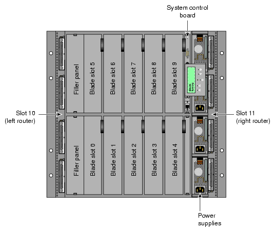
Each blade in individual rack unit (IRU) has a IRU blade slot ID as show in Figure 2-1.
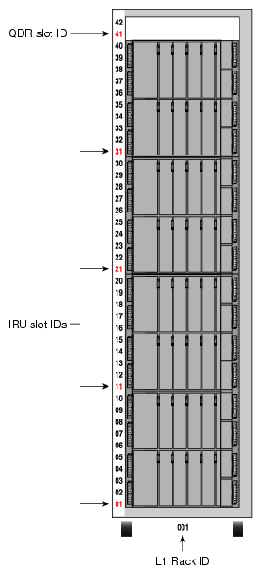
On an Altix 450 and Altix 4700 system, each IRU and Dense router must have a valid and unique rack and module ID. Module IDs should match the UPOS number on the 42U rack that aligns with the bottom of the IRU or Dense router (see Figure 2-2). You can assign a rack ID to the L1 controller, but not the L2, as follows:
RackID = 100 * L1 rack number + L1 slot number
The L2 generates its rack ID from the rack and slot of the local L1.
You can set the L1 slot number with the L1 brick rs <rack> <slot> command. The L1 controller must be rebooted for the new rack and slot number to take effect.
Blades are referenced by the unique rack and module ID of an IRU or racks and slot or bay locations. These values are stored in non-volatile memory on the L1. Virtually all system controller communication requires that each blade have a valid and unique rack and slot. If a brick does not have these, the output of an L2 config command will reflect that as shown in the following example:
L2> config 137.38.88.82.1.0 ---c-- (no rack/slot set) L2> |
If you set the rack and slot ID of an L1 to 001.07, the L2 prompt displays the following rack ID:
hostname-107-L2> |
You can use the L1 blade command to display information about blades on your Altix 450 or Altix 4700 system, as follows:
001c03-L1>blade
Slot# [name]     Enabled       SN       Blade Type       Current State
--------------------------   ------   --------------     -------------
  0   [B0]       Enabled     NTT911   BaseIO             Power Off
  1   [B1]       Enabled              <empty slot>
  2   [B2]       Enabled     NSH576   IP73_667           Power Off
  3   [B3]       Enabled     NSH435   IP73_667           Power Off
  4   [B4]       Enabled              <empty slot>
  5   [B5]       Enabled              <empty slot>
  6   [B6]       Enabled     NSH444   IP73_667           Power Off
  7   [B7]       Enabled     NSH438   IP73_667           Power Off
  8   [B8]       Enabled     NSH430   IP73_667           Power Off
  9   [B9]       Enabled              <empty slot>
 10   [RTRL]     Enabled     NSV633   DUAL_ROUTER        Power Off
 11   [RTRR]     Enabled     NSV627   DUAL_ROUTER        Power Off
001c03-L1>
|
For more information on the L1 blade command, see “blade” in Chapter 3.
For more information on blades, IRUs and Dense routers, see the SGI Altix 4700 System User's Guide.
A single SGI ProPack for Linux server can be divided into multiple distinct systems, each with its own console, root filesystem, and IP network address. Each of these software-defined group of processors are distinct systems referred to as a partition. Each partition can be rebooted, loaded with software, powered down, and upgraded independently. The partitions communicate with each other over an SGI NUMAlink connection. Collectively, all of these partitions compose a single, shared-memory cluster.
You can use the Connect to System Controller task of the SGIconsole Console Manager GUI to connect to the L2 controller of the system you want to partition. The L2 controller must appear as a node in the SGIconsole configuration. For information on how to use SGIconsole, see the Console Manager for SGIconsole Administrator's Guide.
For detailed instructions on how to use the L2 controller commands to partition a system, see “System Partitioning” in the Linux Configuration and Operations Guide.
Threading in a software application splits instructions into multiple streams so that multiple processors can act on them.
Hyper-Threading (HT) Technology, developed by Intel Corporation, provides thread-level parallelism on each processor, resulting in more efficient use of processor resources, higher processing throughput, and improved performance. One physical CPU can appear as two logical CPUs by having additional registers to overlap two instruction streams or a single processor can have dual-cores executing instructions in parallel.
On dual-socket SGI Altix 450 or Altix 4700 systems, the basic CPU layout is as follows:
CPU A Socket 0 Primary Core CPU B Socket 0 Secondary Core CPU C Socket 1 Primary Core CPU D Socket 1 Secondary Core |
In this configuration, Hyper-Threading is not supported. Even if you disable secondary cores using the cpu d command, you cannot turn HT on because you have disabled that cpu (HT or secondary) via the L2 controller. Direct control of CPUs with the L2 cpu commands are available to alter this basic combination.
On single-socket SGI Altix 450 or Altix 4700 systems, the basic CPU layout is as follows:
CPU A Socket 0 Primary Core CPU B Socket 0 HT CPU C Socket 0 Secondary Core CPU D Socket 0 HT |
In this configuration you can enable or disable HT with the ht e or ht d commands, respectively, and affect the CPU B/D combination. Direct control of CPUs with L2 cpu commands are available to alter this basic combination. The system must be powered down when HT is enabled or disabled, as follows:
pwr d r * s * cpu ht [e|d] pwr u |
For more information about using HT, see “Using Cpusets with Hyper-Threads” in the Linux Resource Administration Guide.
This section lists and describes the status and error messages generated by the L1 and L2 controllers. It also explains how to resolve the errors, if action is necessary.
The L1 controller front panel display, located on the front panel of individual bricks, consists of a 2-line, 12-character liquid crystal display (LCD) that provides the following:
Brick identification
System status
Warning of required service or failure
Identification of failed components
Note: Besides the L1 control display, if you have an L2 controller, you can see the L1 controller messages on the L2 controller touch display located on the front door of the leftmost compute rack (position 001). If you have a system console, you can also see the L1 controller messages on your system console.
Table 2-2 lists the L1 controller messages.
| Note: Note that in Table 2-2, a voltage warning occurs when a supplied level of voltage is below or above the nominal (normal) voltage by 10 percent. A voltage fault occurs when a supplied level is below or above the nominal by 20 percent. |
Table 2-2. L1 Controller Messages
L1 System Controller Message | Message Meaning and Action Needed |
|---|---|
Internal voltage messages: |
|
ATTN: x.xV high fault limit reached @ x.xxV | 30-second power off sequence for the brick (or system, if no backup is available), server, or module. |
ATTN: x.xV low fault limit reached @ x.xxV | 30-second power off sequence for the brick (or system, if no backup is available), server, or module. |
ATTN: x.xV high warning limit reached @ x.xxV | A higher than nominal voltage condition is detected. |
ATTN: x.xV low warning limit reached @ x.xxV | A lower than nominal voltage condition is detected. |
ATTN: x.xV level stabilized @ x.xV | A monitored voltage level has returned to within acceptable limits. |
Fan messages: |
|
ATTN: FAN # x fault limit reached @ xx RPM | A fan has reached its maximum RPM level. The ambient temperature may be too high. Check to see if a fan has failed. |
ATTN: FAN # x warning limit reached @ xx RPM | A fan has increased its RPM level. Check the ambient temperature. Check to see if the fan stabilizes. |
ATTN: FAN # x stabilized @ xx RPM | An increased fan RPM level has returned to normal. |
Temperature messages: low alt. |
|
ATTN: TEMP # advisory temperature reached @ xxC xxF | The ambient temperature at the brick's, server's, or module's air inlet has exceeded 30 ºC. |
ATTN: TEMP # critical temperature reached @ xxC xxF | The ambient temperature at the brick's, server's, or module's air inlet has exceeded 35 ºC. |
ATTN: TEMP # fault temperature reached @ xxC xxF | The ambient temperature at the brick's or server's air inlet has exceeded 40 ºC. |
Temperature messages: high alt. |
|
ATTN: TEMP # advisory temperature reached @ xxC xxF | The ambient temperature at the brick's, server's, or module's air inlet has exceeded 27 ºC. |
ATTN: TEMP # critical temperature reached @ xxC xxF | The ambient temperature at the brick's, server's, or module's air inlet has exceeded 31 ºC. |
ATTN: TEMP # fault temperature reached @ xxC xxF | The ambient temperature at the brick's, server's, or module's air inlet has exceeded 35 ºC. |
Temperature stable message: |
|
ATTN: TEMP # stabilized @ xxC/xxF | The ambient temperature at the brick's, server's, or module's air inlet has returned to an acceptable level. |
Power off messages: |
|
Auto power down in xx seconds | The L1 controller has registered a fault and is shutting down. The message displays every 5 seconds until shutdown. |
Brick or server appears to have been powered down | The L1 controller has registered a fault and has shut down. |
The L2 controller performs the following functions:
Controls resource sharing.
Controls L1 controllers.
Resets the system.
Issues non-maskable interrupts (NMIs).
Displays voltage margin information.
Routes data between upstream devices and downstream devices.
Upstream devices (for example, rack display, console, and modem) provide control for the system, initiate commands for the downstream devices, and act on the messages that they receive from downstream devices.
Downstream devices (for example, C-bricks, the USB hub of the R-brick, and L1 controllers of the bricks) perform the actions that are specified by the L2 controller commands, send responses to the L2 controller that indicate the status of the commands, and send error messages to the L2 controller.
Allows remote maintenance.
You use the L2 controller touch display to do the following:
Power the system on and off.
Monitor voltage margins.
Reset the system
Enter a non-maskable interrupt (NMI).
The L2 controller also monitors and generates status and error messages related to the rack chassis items, such as the power bay and other rack items. The L2 controller also displays status and error messages generated by each individual brick's L1 controller. (See “L1 Controller Tasks and Messages” for L1 controller message descriptions.)
The L2 controller information is displayed on the L2 controller touch display located in the front door of your server system. (The actual L2 controller is located on the top of your rack enclosure.)
| Note: If you have a system console, you can also see the L2 controller messages on the system console. |