This appendix contains technical specification information about your system, as follows:
Table A-1 summarizes the Altix ICE 8200 series configuration ranges. Note that while each compute/memory board can house either one or two processors; each processor socket houses two or four processor “cores”.
Table A-1. Altix ICE 8200 Series Configuration Ranges
Category | Minimum | Maximum |
|---|---|---|
Processors | 8 processor cores (2 blades)[a] | 512 processor cores per rack |
Individual Rack Units (IRUs) | 1 per rack | 4 per rack |
Compute/memory blade DIMM capacity | 2 DIMMs per blade (4 MB minimum per blade)[b] | 8 DIMMs per blade |
System main memory DIMMs | 8 per IRU | 128 per IRU (512 per rack) |
Chassis management blades | One per IRU | 4 per rack |
InfiniBand switch blades | 2 per IRU | 4 per IRU (16 per rack) |
[a] Compute blades support one or two stuffed sockets each. This is a total of four or eight cores per blade. [b] Eight MB minimum memory per bladeis required for systems using Scali Manage software. | ||
Table A-2 shows the physical specifications of the Altix ICE system.
Table A-2. Altix ICE 8200 Series Physical Specifications
System Features (single rack) | Specification |
|---|---|
Height | 79.5 in. (201.9 cm) |
Width | 31.3 in. (79.5 cm) |
Depth | 45.8 in. (116.3 cm) |
Weight (full) maximum | ~2,490 lbs. (1,132 kg) approximate |
Shipping weight maximum | ~2,535 lbs. (1,152 kg) approximate |
Voltage range Nominal Tolerance range | North America/International 200-240 VAC /230 VAC 180-264 VAC /180-254 VAC |
Frequency Nominal Tolerance range | North America/International 50/60 Hz /50 Hz 47-63 Hz /47-63 Hz |
Phase required | Single-phase or 3-phase |
Power requirements (max) | 31.63 kVA (31 kW) |
Hold time | 20 ms |
Power cable | 12 ft. (3.66 m) pluggable cords |
Shipping dimensions | Height: 81.375 in. (206.7 cm) |
Access requirements Front Rear Side |
48 in. (121.9 cm) 48 in. (121.9 cm) None |
Table A-3 lists the environmental specifications of the system.
Table A-3. Environmental Specifications
Feature | Specification |
|---|---|
Temperature tolerance | +5 °C (41 °F) to +35 °C (95 °F) (up to 1500 m / 5000 ft.) |
Temperature tolerance | -40 °C (-40 °F) to +60 °C (140 °F) |
Relative humidity | 10% to 80% operating (no condensation) |
Heat dissipation Altix ICE (rack) |
Approximately 105.8 kBTU/hr maximum (based on 31 kW) |
Cooling requirement | Ambient air or optional water cooling |
Air flow: intake (front), exhaust (rear) | Approximately 6,000 CFM (normal operation) 4,000 CFM typical |
Maximum altitude | 10,000 ft. (3,049 m) operating |
Acoustical noise level | Less than 65 dBa maximum |
This section contains specifications and port pinout information for the base I/O ports of your system, as follows:
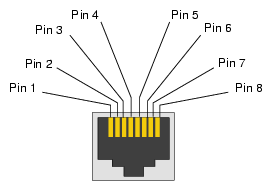
The system auto-selects the Ethernet port speed and type (duplex vs. half-duplex) when the server is booted, based on what it is connected to. Figure A-1 shows the Ethernet port.
Table A-4 shows the cable pinout assignments for the Ethernet port operating in 10/100-Base-T mode and also operating in 1000Base-T mode.
Ethernet 10/100Base-T Pinouts | Gigabit Ethernet Pinouts |
|---|---|
Pins Assignment | Pins Assignment |
1 Transmit + | 1 Transmit/Receive 0 + |
2 Transmit – | 2 Transmit/Receive 0 – |
3 Receive + | 3 Transmit/Receive 1 + |
4 NU | 4 Transmit/Receive 2 + |
5 NU | 5 Transmit/Receive 2 – |
6 Receive – | 6 Transmit/Receive 1 – |
7 NU | 7 Transmit/Receive 3 + |
8 NU | 8 Transmit/Receive 3 – |
NU = Not used
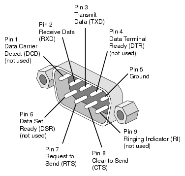
The IRU's chassis management control boards have 9-pin serial interface connectors. These ports are capable of transferring data at rates as high as 230 kbps. Other features of the ports include the following:
Programmable data, parity, and stop bits
Programmable baud rate and modem control
Figure A-2 shows an example serial port.
Table A-5 shows pinout assignments for the 9-pin male DB-9 connector.
Pin | Assignment | Description |
|---|---|---|
1 | DCD | Data carrier detect |
2 | RXD | Receive data |
3 | TXD | Transmit data |
4 | DTR | Data terminal ready |
5 | GND | Signal ground |
6 | DSR | Data set ready |
7 | RTS | Request to send |
8 | CTS | Clear to send |
9 | RI | Ring indicator |

