This chapter provides the following sections to help you troubleshoot your system:
Table 6-1 lists recommended actions for problems that can occur. To solve problems that are not listed in this table, contact your SGI system support engineer (SSE).
Table 6-1. Troubleshooting Chart
Recommended Action | |
|---|---|
The system will not power on. | Ensure that the power cords of the IRU are seated properly in the power receptacles. Ensure that the PDU circuit breakers are on and properly connected to the wall source. If the power cord is plugged in and the circuit breaker is on, contact your SSE. |
An individual IRU will not power on. | Ensure the power cables of the IRU are plugged in. View the CMC output from your system administration controller console. If the CMC is not running, contact your SSE. |
The system will not boot the operating system. | Contact your SSE. |
The Service Required LED illuminates on an IRU. | View the CMC display of the failing IRU; contact your administrator or SSE for help as needed. |
The PWR LED of a populated PCI slot in a support server is not illuminated. | Reseat the PCI card. |
The Fault LED of a populated PCI slot in a support server is illuminated (on). | Reseat the PCI card. If the fault LED remains on, replace the PCI card. |
The amber LED of a disk drive is on. | Replace the disk drive. |
There are a number of LEDs on the front of the IRUs that can help you detect, identify and potentially correct functional interruptions in the system.
The following subsections describe these LEDs and ways to use them to understand potential problem areas.
Each power supply installed in an IRU has a single bi-color (green/amber) status LED.
The LED will either light green or amber (yellow), or flash green or yellow to indicate the status of the individual supply. See Table 6-2 for a complete list.
Table 6-2. Power Supply LED States
Power supply status | Green LED | Amber LED |
|---|---|---|
No AC power to the supply | Off | Off |
Power supply has failed | Off | On |
Power supply problem warning | Off | Blinking |
AC available to supply (standby) but IRU is off | Blinking | Off |
Power supply on (IRU on) | On | Off |
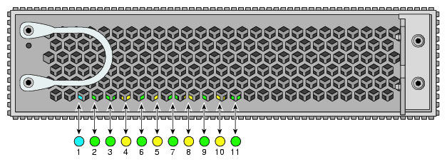
Each compute/memory blade installed in an IRU has a total of eleven LED indicators arranged in a single row behind the perforated sheetmetal of the blade. The LEDs are located in the front lower left section of the compute blade and are visible through the screen of the compute blade, see Figure 6-1. The functions of the LED status lights are as follows:
UID - Unit identifier - this blue LED is used during troubleshooting to find a specific compute node. The LED can be lit via software to aid in locating a specific compute node.
CPU Power OK - this green LED lights when the correct power levels are present on the processor(s).
IB0 link - green LED lights when a link is established on the internal InfiniBand 0 port
IB0 active - this amber LED flashes when IB0 is active (transmitting data)
IB1 link - green LED lights when a link is established on the internal InfiniBand 1 port
IB1 active - this amber LED flashes when IB1 is active (transmitting data)
Eth1 link - this green LED is illuminated when a link as been established on the system control Eth1 port
Eth1 active - this amber LED flashes when Eth1 is active (transmitting data)
Eth2 link - this LED indicates the compute blade's BMC Ethernet interface link status
Eth2 active - this LED indicates the compute blade's BMC Ethernet activity status
BMC heartbeat - this green LED flashes when the blade's BMC boots and is running normally. No illumination, or an LED that stays on solidly indicates the BMC failed.

Note: Compute blades that shipped in 2007 and early 2008 have only ten LED status lights. The functions of the first ten LEDs are the same on older and newer blades.
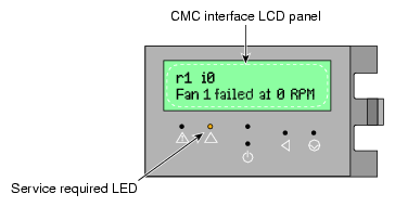
Environmental “out-of-bounds” and chassis hardware failure conditions are reported on the chassis management panel. For individual rack units that experience a chassis-related component failure, a message appears on the CMC interface panel. This message is accompanied by the lighting of the amber “Service Required” LED on the panel's front face (second from left). In the example shown in Figure 6-2, IRU 0 in rack 1 has experienced a fan failure. This type of information can be useful in helping your administrator or service provider identify and quickly correct hardware problems.

