This chapter describes the function and physical components of the administrative/controller server modules in the following sections:
For purposes of this chapter “administration/controller module” is used as a catch-all phrase to describe the stand-alone servers that act as management infrastructure controllers. The specialized functions these servers perform within the ICE system can include:
Administration
Rack leader controller (RLC)
Fabric management
Login
Batch
I/O gateway (storage)
User interfaces consist of the Compute Cluster Administrator, the Compute Cluster Job Manager, and a Command Line Interface (CLI). Management services include job scheduling, job and resource management, Remote Installation Services (RIS), and a remote command environment. The 1U administrative controller server is connected to the system via a Gigabit Ethernet link, (it is not directly linked to the system's InfiniBand communication fabric).
| Note: The system management software runs on the administrative node, RLC and service nodes as a distributed software function. The system management software performs all of its tasks on the ICE system through an Ethernet network. |
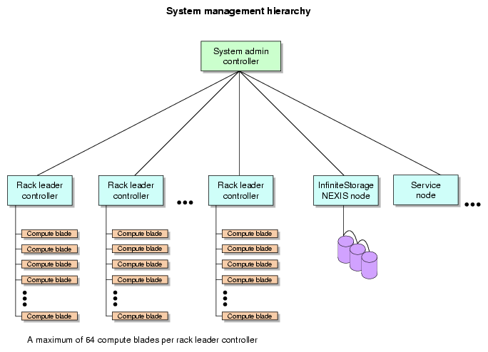
The administrative controller server is at the top of the distributed management infrastructure within the ICE system. The overall ICE 8200 series management is hierarchical (see Figure 5-1), with the RLC(s) communicating with the compute nodes via CMC.
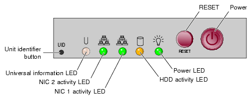
The system administrative controller unit acts as the ICE system interface to the “outside world”, typically a local area network (LAN). The administrative unit control panel features are shown in Figure 5-2.
Table 5-1. System administrative server control panel functions
Functional feature | Functional description |
|---|---|
Unit identifier button | Pressing this button lights an LED on both the front and rear of the server for easy system location in large configurations. The LED will remain on until the button is pushed a second time. |
Universal information LED | This multi-color LED blinks red quickly, to indicate a fan failure and blinks red slowly for a power failure. A continuous solid red LED indicates a CPU is overheating. This LED will be on solid blue or blinking blue when used for UID (Unit Identifier). |
NIC 2 Activity LED | Indicates network activity on LAN 2 when flashing green. |
NIC 1 Activity LED | Indicates network activity on LAN 1 when flashing green. |
Disk activity LED | Indicates drive activity when flashing. |
Power LED | Indicates power is being supplied to the server's power supply units. |
Reset button | Pressing this button reboots the server. |
Power button | Pressing the button applies/ removes power from the power supply to the server. Turning off power with this button removes main power but keeps standby power supplied to the system. |
An MPI job is started from the rack leader controller server and the sub-processes are distributed to the system blade compute nodes. The main process on the RLC server will wait for the sub-processes to finish. For very large systems or systems that run many MPI jobs, multiple RLC servers may be used to distribute the load (one per rack).
The 1U rack leader server may also run the software for login purposes as the system “login node”. In other optional cases the RLC 1U server may be used to run the “batch node” function.
Batch or login functions may be run on individual separate service nodes, especially when the system is a large scale multi-rack installation or has a large number of users. See the section “Modularity and Scalability” in Chapter 3 for a list of administration and support server types and additional functional descriptions.
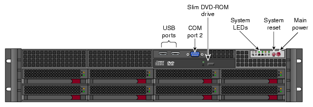
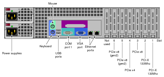
For systems that require a separate login, batch, I/O, fabric management, or other service node; a 2U server option is available. Figure 5-4 and Figure 5-5 show front and rear views of the 2U service node. For more information, see the SGI Altix XE250 User's Guide, (P/N 007-5467-00x).


