This chapter provides an overview of the physical and architectural aspects of your SGI Altix Integrated Compute Environment (ICE) 8200 series system. The major components of the Altix ICE systems are described and illustrated.
Because the system is modular, it combines the advantages of lower entry-level cost with global scalability in processors, memory, InfiniBand connectivity and I/O. You can install and operate the Altix ICE 8200 series system in your lab or server room. Each 42U SGI rack holds from one to four 10U-high individual rack units (IRUs) that support up to sixteen compute/memory cluster sub modules known as “blades.” These blades are single printed circuit boards (PCBs) with ASICS, processors, memory components and I/O chip sets mounted on a mechanical carrier. The blades slide directly in and out of the IRU enclosures. Every processor node blade contains at least two dual-inline memory modules (DIMM) memory units.
Each blade supports two processor sockets that can have two or 4 processor cores. A maximum system size of 64 compute/memory blades (512 cores) per rack is supported at the time this document was published. Optional chilled water cooling may be required for large processor count rack systems. Customers wishing to emphasize memory capacity over processor count can choose blades configured with only one processor installed per blade. Contact your SGI sales or service representative for the most current information on these topics.
The SGI Altix ICE 8200 series systems can run parallel programs using a message passing tool like the Message Passing Interface (MPI). The ICE blade system uses a distributed memory scheme as opposed to a shared memory system like that used in the SGI Altix 450 or Altix 4700 high-performance compute servers. Instead of passing pointers into a shared virtual address space, parallel processes in an application pass messages and each process has its own dedicated processor and address space. This chapter consists of the following sections:
The basic enclosure within the Altix ICE system is the 10U high (17.5 inch or 44.45 cm) “individual rack unit” (IRU). The IRU enclosure supports a maximum of 16 compute/memory blades, up to eight power supplies, one chassis manager interface and two or four InfiniBand architecture I/O fabric switch interface blades. Each IRU comes with two or four InfiniBand fabric switch blades.
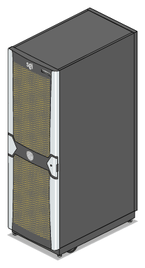
The 42U rack for this server houses all IRU enclosures, option modules, and other components; up to 128 processor sockets (512 processor cores) in a single rack. Note that optional water chilled rack cooling may be required for systems with high processor counts.
Figure 3-1 shows an example configuration of a single-rack Altix ICE 8200 server.
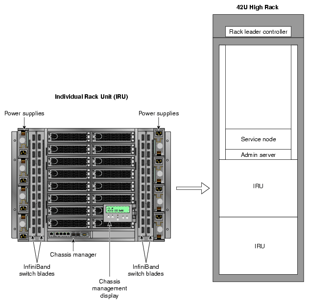
The system requires a minimum of one 42U tall rack with three single-phase power distribution units (PDUs) for the first IRU installed in the rack. Each single-phase PDU has 5 outlets (eight are required to support the eight power supplies that can be installed in each IRU). Subsequent IRU's can be supported by two single-phase PDUs each. Figure 3-2 shows an IRU and Rack.
The three-phase PDU has 18 outlets (12 connections are required to support one IRU, an administrative node, RLC, and a service node installed in the rack). Note that the lighted door function requires a power outlet from the PDU also.
You can also add additional RAID and non-RAID disk storage to your rack system.
The Altix ICE 8200 series of computer systems are based on an InfiniBand I/O fabric. This concept is supported and enhanced by using the technologies described in the following subsections.
The Memory Controller HUB (MCH) is a single flip chip ball grid array (FCBGA) which supports the following core platform functions:
System bus interface for the processors
Memory control sub-system
PCI Express ports
Fully buffered DIMM (FBD) thermal management
Memory (DIMM) sub-system
ESB-2 I/O controller
These functions are elaborated in the following subsections. Note that this architecture does not support memory mirroring on the system compute blades.
The system bus is configured for symmetric multi-processing across two independent point-to-point front side bus interfaces that connect the dual-core or quad-Core Intel Xeon processors. Each front side bus on the MCH uses a 64-bit wide data bus. The data bus is capable of addressing up to 128 GB of memory. The MCH is the priority agent for both front side bus interfaces, and is optimized for one processor on each bus.
Each cluster node board supports two dual-core or quad-core Intel Xeon processors. Previous generations of Intel Xeon processors are not supported on the node board.
The MCH provides four channels of Fully Buffered DIMM (FB-DIMM) memory. Each channel can support up to 2 Dual Ranked Fully Buffered (DDR2) DIMMs. FB-DIMM memory channels are organized into two branches with a capability to support RAID 1 (mirroring). The MCH can support up to 8 DIMMs with a maximum memory size dependent on the capacity of the individual DIMMs. The total physical memory available is cut in half when used in a mirrored (RAID 1) configuration.
Using all four channels a maximum read bandwidth of 21 GB/s for four FB-DIMM channels is possible. This option also provides up to 12.8 GB/s of write memory bandwidth for four FB-DIMM channels.
A minimum of one dual-inline-memory module (DIMM) set (2 DIMMs) is required for each blade. Blades are supported with 2, 4, 6, or 8 installed DIMMs.
| Note: Regardless of the number of DIMMs installed, a minimum of 4GB of DIMM memory is recommended for each compute blade. Systems using Scali Manage software should have a minimum of 8GB of DIMM memory installed on each blade. Failure to meet these requirements may have impacts on overall application performance. |
A maximum of four DIMM sets (8 total DIMMs) can be installed in a compute blade. Each set of DIMMs (pair) on a blade must be the same capacity and functional speed. When possible, it is generally recommended that all blades within an IRU use the same number and capacity (size) DIMMs.
Each blade in the IRU may have a different total DIMM capacity. For example, one blade may have eight DIMMs, and another may have only two. Note that while this difference in capacity is acceptable functionally, it may have impacts on compute “load balancing” within the system.
The ESB-2 is a multi-function device that provides the following four distinct functions:
IO controller
PCI-X bridge
Gb Ethernet controller
Baseboard Management Controller (BMC)
Each function within the ESB-2 has its own set of configuration registers. Once configured, each appears to the system as a distinct hardware controller. The primary role of the ESB-2 is to provide the Gigabit Ethernet interface between the Chassis Management Controller (CMC) and the Baseboard Management Controller (BMC). Each blade`s node board uses the following features:
Dual GbE MAC
Baseboard Management Controller (BMC)
Power management
Figure 3-3 shows a functional block diagram of the Altix ICE 8200 series system IRU compute/memory blades, InfiniBand interface, and component interconnects.
The main features of the Altix ICE 8200 series server systems are introduced in the following sections:
The Altix ICE 8200 series systems are modular systems. The components are primarily housed in building blocks referred to as individual rack units (IRUs). However, other “free-standing” Altix compute servers are used to administer, access and enhance the ICE 8200 series systems. Additional optional mass storage may be added to the system along with additional IRUs. You can add different types of stand-alone module options to a system rack to achieve the desired system configuration. You can configure and scale IRUs around processing capability, memory size or InfiniBand fabric I/O capability. The air-cooled IRU enclosure has redundant, hot-swap fans and redundant, hot-swap power supplies. The water-chilled rack option expands a single rack's compute density with added heat dissipation capability for the IRU components.
A number of free-standing (non-blade) compute and I/O servers (nodes) are used with Altix ICE 8200 series systems in addition to the standard two-socket blade-based compute nodes. These free-standing units are:
System administration controller
System rack leader controller (RLC) server
Service nodes with the following functions:
Fabric management service node (often incorporated as part of the RLC)
Login node
Batch node
I/O gateway node
As a general rule, each ICE system will have at least one system administration controller, one rack leader controller (RLC) server and one service node. The administration controller and RLC are stand-alone 1U servers. The service nodes are stand-alone non-blade 2U-high servers.
The following subsections further define the free-standing unit functions described in the previous list.
As a general rule, there is one stand-alone administration controller server and I/O unit per system rack. The system administration controller is a non-blade Altix 1U server system. The administration controller server is used to install ICE system software, administer that software and monitor information from all the nodes in the system.
A significant operating factor for the system administration controller node is the file system structure. If the administration node is NFS-mounting a network storage system outside the ICE system, input data and output results will need to pass through the administration server for each job. Multiple system administration servers distribute this load. The exact number of system administration nodes an ICE system requires for maximum performance is size and application dependent.
Another factor is the number of interactive logins. Since the system administration controller node is the only server in the ICE 8200 system that is connected to the external network, this is where interactive logins occur. Some ICE systems are configured with dedicated “login” service nodes for this purpose. In this case, you might configure multiple “service nodes” but have all but one devoted to interactive logins as “login nodes”, see the “I/O Gateway Node”.
A rack leader controller (RLC) server is generally used by administrators to provision and manage the system using SGI's cluster management (CM) software. There is generally only one leader controller per rack and it is a non-blade “stand-alone” 1U server. The rack leader controller is guided and monitored by the system administration server. It in turn monitors, pulls and stores data from the compute nodes of all the IRUs within the rack. The rack leader then consolidates and forwards data requests received from the IRU's blade compute nodes to the administration server. The leader controller may also supply boot and root file sharing images to the compute nodes in the IRUs.
For large systems or systems that run many MPI jobs, multiple RLC servers may be used to distribute the load. The first RLC in the ICE system is the “master” controller server. Additional RLCs are slaved to the first RLC (which is usually installed in rack 1). The second RLC runs the same fabric management image as the primary “master” RLC. Check with your SGI sales or support representative for configurations that can “fail over” and continue to support the ICE system's fabric management without halting the overall system.
In most ICE configurations the fabric management function is handled by the rack leader controller (RLC) node. The RLC is an independent server node that is not part of an IRU. See the “Rack Leader Controller” subsection for more detail. The fabric management software runs on one or more RLC nodes and monitors the function of and any changes in the Infiniband fabrics of the system. It is also possible to host the fabric management function on a dedicated service node, thereby moving the fabric management function from the rack leader node and hosting it on an additional server(s). A separate fabric management server would supply fabric status information to the RLC server periodically or upon request. As with the rack leader controller server, only one per rack is supported.
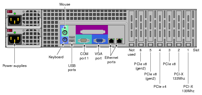
The functionality of the service nodes listed in this subsection are all services that can technically run on a single hardware server unit. Or, in the case of the fabric management function, it can be co-resident on the rack leader controller node. As the system scales, you can add more servers (nodes) and dedicate them to these service functions if the size of the system requires it. However you can also have a smaller system where many of the services are combined on just a single service node. Figure 3-4 shows a rear view of a 1U service node (also used for system administration and RLC).
The login server function within the ICE system can be functionally combined with the I/O gateway server node function in some configurations. One or more per system are supported. Very large systems with high levels of user logins may use one or more dedicated login server nodes. The login node functionality is generally used to create and compile programs, and additional login server nodes can be added as the total number of user logins increase. The login server is usually the point of submittal for all message passing interface (MPI) applications run in the system. An MPI job is started from the login node and the sub-processes are distributed to the ICE system's compute nodes.
Figure 3-5 shows the rear connectors and interface slots on a 2U service node.
The batch server function may be combined with login or other service nodes for many configurations. Additional batch nodes can be added as the total number of user logins increase. Users login to a batch server in order to run batch scheduler portable-batch system/load-sharing facility (PBS/LSF) programs. Users login or connect to this node to submit these jobs to the system compute nodes.
The I/O gateway server function may be combined with login or other service nodes for many configurations. If required, the I/O gateway server function can be an optional 1U, 2U or 5U stand-alone server within the ICE system. One or more I/O gateway nodes are supported per system, based on system size and functional requirement. The node may be separated from login and/or batch nodes to scale to large configurations.Users login or connect to submit jobs to the compute nodes. The node acts as a gateway from InfiniBand to various types of storage, such as direct-attach, Fibre Channel, or NFS.
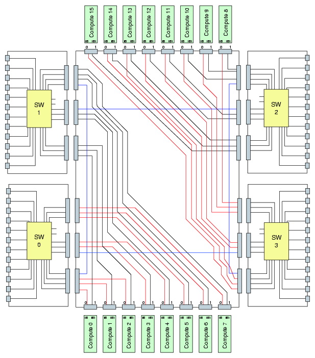
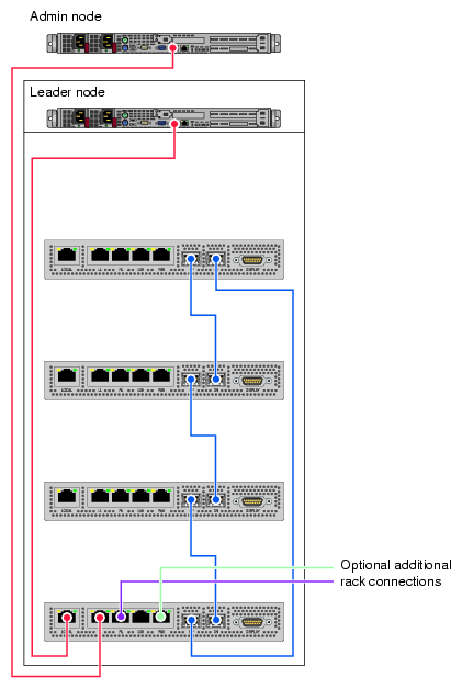
In certain multiple-IRU configurations the chassis managers in each IRU may be interconnected and wired to the administrative server and the rack leader controller (RLC) server. Figure 3-6 shows an example diagram of the interconnects. Note that the scale of the CMC drawings is adjusted to clarify the interconnect locations.
The Altix ICE 8200 server series components have the following features to increase the reliability, availability, and serviceability (RAS) of the systems.
Power and cooling:
IRU power supplies are redundant and can be hot-swapped under most circumstances. Note that this might not be possible in a “fully loaded” IRU.
A rack-level water chilled cooling option is available for systems with high-density configurations.
IRUs have overcurrent protection at the blade and power supply level.
Fans are redundant and can be hot-swapped.
Fans run at multiple speeds in the IRUs. Speed increases automatically when temperature increases or when a single fan fails.
System monitoring:
Chassis managers monitor the internal voltage, power and temperature of the IRUs.
Each IRU and each blade/node installed has failure LEDs that indicate the failed part; LEDs are readable at the front of the IRU.
Systems support remote console and maintenance activities.
Error detection and correction
External memory transfers are protected by cyclical redundancy correction (CRC) error detection. If a memory packet does not checksum, it is retransmitted.
Nodes within each IRU exceed SECDED standards by detecting and correcting 4-bit and 8-bit DRAM failures.
Detection of all double-component 4-bit DRAM failures occur within a pair of DIMMs.
32-bits of error checking code (ECC) are used on each 256 bits of data.
Automatic retry of uncorrected errors occurs to eliminate potential soft errors.
Power-on and boot:
Automatic testing occurs after you power on the system nodes. (These power-on self-tests or POSTs are also referred to as power-on diagnostics or PODs).
Processors and memory are automatically de-allocated when a self-test failure occurs.
Boot times are minimized.
The Altix ICE 8200 series system features the following major components:
42U rack. This is a custom rack used for both the compute and I/O rack in the Altix ICE 8200 series. Up to 4 IRUs can be installed in each rack. There is 2U of space reserved for the 1U administrative controller server and 1U rack leader controller server.
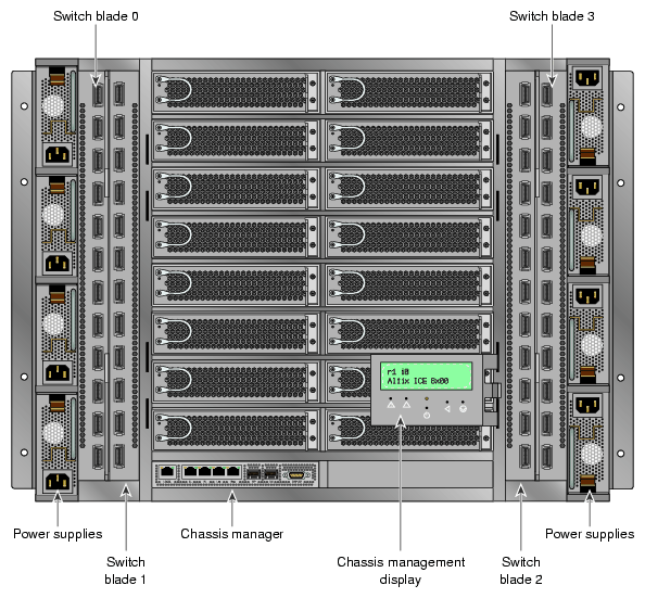
Individual Rack Unit (IRU). This enclosure contains the compute/memory blades, chassis manager, InfiniBand fabric I/O blades and front-access power supplies for the Altix ICE 8200 series computers. The enclosure is 10U high. Figure 3-7 shows the Altix ICE 8200 series IRU system components.
Compute/memory blade. Holds one or two processor sockets (dual or quad-core) and 2, 4, 6 or 8 memory DIMMs.
1U Administrative server with PCIe/PCI-X expansion. This server node supports an optional console, administrative software and three PCI Express option cards.
1U (Rack leader controller). The 1U rack leader server can also be used as an optional login, batch, or fabric functional node.
2U Service node. An optional 2U service node may be used as a login, batch, or fabric functional node when system size or configuration requires a dedicated server for these functions.
5U (I/O server controller). The optional 5U server node is offered with certain configurations needing higher performance I/O access for the ICE system. It offers multiple I/O options and higher performance processors than the 1U or 2U server nodes.

Note: PCIe options may be limited, check with your SGI sales or support representative.
IRUs in the racks are not identified using standard units. A standard unit (SU) or unit (U) is equal to 1.75 inches (4.445 cm). IRUs within a rack are identified by the use of module IDs 0, 1, 2, and 3, with IRU 0 residing at the bottom of each rack. These module IDs are incorporated into the host names of the CMC (i0c, i1c, etc.) and the compute blades (r1i0n0, r1i1n0, etc.) in the rack.
Each rack is numbered with a single-digit number sequentially beginning with (0). A rack contains IRU enclosures, administrative and rack leader server nodes, service specific nodes, optional mass storage enclosures and potentially other options. In a single compute rack system, the rack number is always (1). The number of the first IRU will always be zero (0). These numbers are used to identify components starting with the rack, including the individual IRUs and their internal compute-node blades. Note that these single-digit ID numbers are incorporated into the host names of the rack leader controller (RLC) (r1lead) as well as the compute blades (r1i0n0) that reside in that rack.
Availability of optional components for the SGI ICE 8200 series of systems may vary based on new product introductions or end-of-life components. Some options are listed in this manual, others may be introduced after this document goes to production status. Check with your SGI sales or support representative for the most current information on available product options not discussed in this manual.
