This chapter describes the interaction and functions of system controllers in the following sections:
Each IRU has one chassis manager, which is located directly below compute blade slot 0. The chassis manager supports power-up and power-down of the IRU's compute/memory node blades and environmental monitoring of all units within the IRU.
Note that the stand-alone (nodes) such as the administrative server, rack leader controller, or other service nodes and mass storage enclosures do not have a chassis manager.
Figure 2-1 shows an example remote LAN-connected console used to monitor a single-rack Altix ICE 8200 series system.
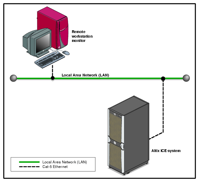
The SGI optional 1U console is a rackmountable unit that includes a built-in keyboard/touchpad, and uses a 17-inch (43-cm) LCD flat panel display of up to 1280 x 1024 pixels. The 1U console attaches to the administrative controller server using PS/2 and HD15M connectors or to a KVM switch (not provided by SGI). The 1U console is basically a “dumb” VGA terminal, it cannot be used as a workstation or loaded with any system administration program.
| Note: While the 1U console is normally plugged into the administrative controller server in the ICE system, it can also be connected to a rack leader controller server in the system for terminal access purposes. |
The 27-pound (12.27-kg) console automatically goes into sleep mode when the cover is closed.
The chassis management control network configuration of your ICE 8200 series machine will depend on the size of the system and the control options selected. Typically, any system with multiple IRUs will be interconnected by the chassis managers in each IRU.
| Note: Mass storage option enclosures are not monitored by the IRU's chassis manager. Most optional mass storage enclosures have their own internal microcontrollers for monitoring and controlling all elements of the disk array. See the owner's guide for your mass storage option for more information on this topic. |
In all Altix ICE 8200 series systems all the system chassis management controllers communicate with each other in the following ways:
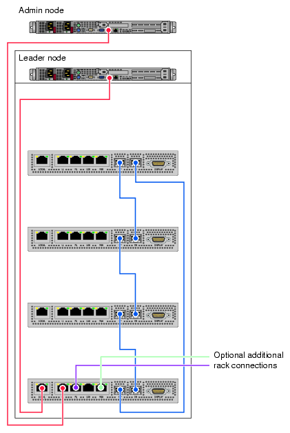
All enclosures within a system communicate with each other through their chassis manager connections (CMC) (note the chassis managers are enlarged for clarity in Figure 2-2).
The CMC does the environmental management for an IRU as well as power control, and provides an ethernet network infrastructure for the management of the system.
The chassis manager in the lower IRU connects to the administration and leader nodes, see the example in Figure 2-2.
The following list summarizes the control and monitoring functions that the CMC performs. Most functions are common across multiple IRUs.
Controls and monitors IRU fan speeds
Reads system identification (ID) PROMs
Monitors voltage levels and reports failures
Monitors the On/Off power sequence
Monitors system resets
Applies a preset voltage to switch blades and fan control boards
Figure 2-3 shows the chassis management controller display panel on the IRU.
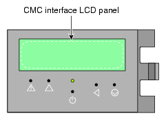
| Note: The CMC front panel display provides rack and IRU identification information and IRU hardware chassis malfunction alerts. See “Chassis Management Panel “Service Required” Notices ” in Chapter 6 for additional information. |
The cpower command is the main interface for all power management commands. You can request power status, power-on and power-off the system with commands entered via the administrative controller server or rack leader controller in the system rack. The cpower commands are communicating with BMCs using the IPMI protocol.
The cpower commands may require several seconds to several minutes to complete, depending on how many IRUs are being queried for status, powered-up, or shut down.
# cpower --system
This command gives the status of all compute nodes in the system.
To power on or power off a specific IRU, enter the following commands:
# cpower --iru --up r1i0 |
The system should respond by powering up the IRU 0 nodes in rack 1. Note that --on is the same as --up. This command does not power-up the system administration (server) controller, rack leader controller (RLC) server or other service nodes.
# cpower --iru --down r1i0 |
This command powers down all the nodes in IRU 0 in rack 1. Note that --down is the same as --off. This command does not power-down the system administration node (server) , rack leader controller server or other service nodes.
See “Console Management Power (cpower) Commands” in Chapter 1 for additional information on power-on, power-off and power status commands. The SGI Tempo System Administrator's Guide, (P/N 007-4993-00x) has more extensive infomation on these topics.