This chapter explains how to operate your new system in the following sections:
Before operating your system, familiarize yourself with the safety information in the following sections:
| Caution: Observe all ESD precautions. Failure to do so can result in damage to the equipment. |
Wear an SGI-approved wrist strap when you handle an ESD-sensitive device to eliminate possible ESD damage to equipment. Connect the wrist strap cord directly to earth ground.
| Warning: Before operating or servicing any part of this product, read the “Safety Information” in Appendix B. |
| Warning: Keep fingers and conductive tools away from high-voltage areas. Failure to follow these precautions will result in serious injury or death. The high-voltage areas of the system are indicated with high-voltage warning labels. |
| Caution: Power off the system only after the system software has been shut down in an orderly manner. If you power off the system before you halt the operating system, data may be corrupted. |
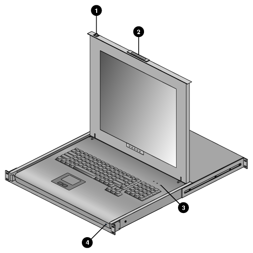
The flat panel console option (see Figure 1-1) has the following listed features:
Slide Release - Move this tab sideways to slide the console out. It locks the drawer closed when the console is not in use and prevents it from accidentally sliding open.
Handle - Used to push and pull the module in and out of the rack.
LCD Display Controls - The LCD controls include On/Off buttons and buttons to control the position and picture settings of the LCD display.
Power LED - Illuminates blue when the unit is receiving power.
A console is defined as a connection to the system (to the administrative “node” server) that provides administrative access to the cluster. SGI offers a rackmounted flat panel console option that attaches to the administrative node's video, keyboard and mouse connectors.
A console can also be a LAN-attached personal computer, laptop or workstation (RJ45 Ethernet connection).
In certain limited cases, a dumb terminal could be used. An RS-232 style serial connection can be used to communicate directly with the administrative node. This connection is typically used for service purposes or for system console access in smaller systems, or where an external ethernet connection is not used or available.
The flat panel rackmount or other optional VGA console connects to the administration node's video and keyboard/mouse connectors as shown in Figure 1-2.
This section explains how to power on and power off individual rack units, or your entire Altix ICE system, as follows:
Entering commands from a system console, you can power on and power off individual IRUs, blade-based nodes, and stand-alone servers, or the entire system.
When using the SGI cluster manager software, you can monitor and manage your server from a remote location (see the SGI Tempo System Administrator's Guide).
You may also monitor and manage your server with tools such as the Voltaire or Intel message passing interface (MPI). For details, see the documentation for the particular tool.
To prepare to power on your system, follow these steps:
Check to ensure that the cabling between the rack's power distribution units (PDUs) and the wall power-plug receptacle is secure.
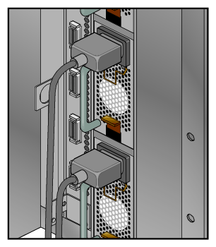
For each individual IRU that you want to power on, make sure that the power cables are plugged into all the IRU power supplies correctly, as shown in Figure 1-3. Setting the circuit breakers on the PDUs to the “On” position will apply power to the IRU and will start the chassis manager in each IRU. Note that the chassis manager in each IRU stays powered on as long as there is power coming into the unit. Turn off the PDU breaker switch that supplies voltage to the IRU if you want to remove all power from the unit.
If you plan to power on a server that includes optional mass storage enclosures, make sure that the power switch on the rear of each PSU/cooling module (one or two per enclosure) is in the 1 (on) position.
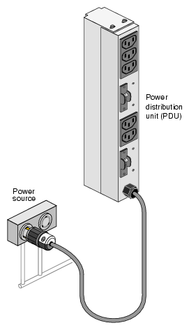
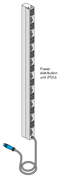
Make sure that all PDU circuit breaker switches (see the examples in Figure 1-4 and Figure 1-5) are turned on to provide power when the system is booted up.
Figure 1-5 shows an example of the three-phase PDU.
The power-on and off procedure varies with your system setup. See the SGI Tempo System Administrator's Guide, (P/N 007-4993-00x) for a more complete description of system commands.
| Note: The cpower commands are normally run through the administration node. If you have a terminal connected to an administrative server with a serial interface, you should be able execute these commands. |
This section provides an overview of the console management power (cpower) commands for the SGI Altix ICE system.
The cpower commands allow you to power up, power down, reset, and show the power status of multiple or single system components or individual racks.
The cpower command is, as follows:
cpower <option...> <target_type> <action> <target> |
The cpower command accepts the following arguments as described in Table 1-1.
Table 1-1. cpower option descriptions
Argument | Description | Option |
|
|---|---|---|---|
--noleader | Do not include rack leader nodes. Valid with rack and system domains only. | ||
--noservice | Do not include service nodes. | ||
--ipmi | Uses ipmitool to communicate. | ||
--ssh | Uses ssh to communicate. | ||
--intelplus | Use the “-o intelplus option” for ipmitool [default]. | ||
--verbose | Print additional information on command progress. | ||
--noexec | Display but do not execute commands that affect power. | ||
Target_type |
| ||
--node | Apply the action to a node or nodes. Nodes can be blade compute nodes (inside an IRU), administration server nodes, rack leader controller nodes or service nodes. | ||
--iru | Apply the action at the IRU level | ||
--rack | Apply the action to all components in a rack | ||
--system | Apply the action to the entire system. You must not specify a target with this type. | ||
--all | Allows the use of wildcards in the target name | ||
Action |
| ||
--status | Shows the power status of the target [default] | ||
--up | --on | Powers up the target | ||
--down | --off | Powers down the target | ||
--cycle | Power cycles the target | ||
--reboot | Reboot the target, even if it is already booted. Wait for all targets to boot. | ||
--halt | Shutdown the target, but do not power it off. Wait for targets to shut down. | ||
--help | Usage and help text |
| Note: If you include a rack leader controller in your wildcard specification, and a command that may take it offline, you will see a warning intended to prevent accidental resets of the RLC, as that could make the rack unreachable. |
Table 1-2. cpower example command strings
Command | Status/result |
|---|---|
# cpower --system --up | Powers up all nodes in the system (--up is the same as --on). |
# cpower --rack r1 | Determines the power status of all nodes in rack 1 (including the RLC), except CMCs. |
# cpower --system | Provides status of every compute node in the system. |
# cpower --boot --rack r1 | Boots any nodes in rack 1 not already online. |
# cpower --system --down | Completely powers down every node in the system. Use only if you want to shut down all nodes (see the next example). |
# cpower --halt --system --noleader --noservice | Shuts down (halts) all the IRU compute nodes in the system, but not the administrative controller server, rack leader controller or other service nodes. |
# cpower --boot r1i0n8 | Command tries to specifically boot rack 1, IRU0, node 8. |
# cpower --halt --rack r1 | Will halt and then power off all of the computer nodes in parallel located in rack 1, then halts the rack leader controller. Use --noleader if you want the RLC to remain on. |
See the SGI Tempo System Administrator's Guide, (P/N 007-4993-00x) for more information on cpower commands. See the section “System Power Status” in Chapter 2 for additional related console information.
You can monitor your Altix ICE 8200 server from the following sources:
An optional flat panel rackmounted monitor with PS2 keyboard/mouse can be connected to the administration server node for basic monitoring and administration of the Altix system. See the section “Console Connections” for more information. SLES 10 or higher is required for this option.
You can attach an optional LAN-connected console via secure shell (ssh) to an Ethernet port adapter on the administration controller server. You will need to connect either a local or remote workstation/PC to the IP address of the administration controller server to access and monitor the system via IPMI.
See the Console Management section in the SGI Tempo System Administrator's Guide, (P/N 007-4993-00x) for more information on the open source console management package.
These console connections enable you to view the status and error messages generated by your Altix ICE 8200 system. You can also use these consoles to input commands to manage and monitor your system. See the section “System Power Status” in Chapter 2, for additional information.
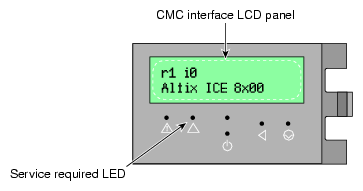
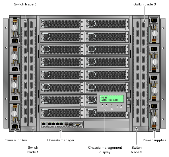
The chassis management front panel is an additional source of IRU status information. Figure 1-6 shows an example of the panel and the functions it reports. Figure 1-7 shows a front view of a system IRU and the location of the chassis management panel.
The CMC panel offers basic information on the rack (its assigned number) and various types of status information regarding the IRU chassis components. For additional information, see “Chassis Management Panel “Service Required” Notices ” in Chapter 6.
PCI/PCI-X and PCIe based I/O sub-systems are sited in the administrative controller server and rack leader controller systems used with the system IRUs. These are the primary configurable I/O system interfaces for the Altix ICE 8200 systems. See the particular server's user guide for information on installing optional I/O cards or other components.
| Note: The IRU uses four InfiniBand switch blades in certain configurations and two in others. |
