This appendix contains technical specification information about your system, as follows:
Table A-1 summarizes the Altix UV 100 system configuration ranges. Note that while each compute/memory board can house two processor sockets; each socket can potentially hold six, eight or ten processor “cores”.
Table A-1. Altix UV 100 System Configuration Ranges
Category | Minimum | Maximum |
|---|---|---|
Processors | 12 processor cores (1 blade)[a] | 768 processor cores |
Individual Rack Units (IRUs) | 1 per rack | 12 per rack |
Blades per IRU | 1 per IRU | 2 per IRU |
Compute/memory blade DIMM capacity | 8 DIMMs per blade | 16 DIMMs per blade |
CMC units | 1 per IRU | 1 per IRU |
Number of BaseIO riser enabled blades | One per SSI | One per SSI |
[a] Dual-socket blades support 12 to 20 cores per blade. | ||
Table A-2 shows the physical specifications of the Altix UV 100 system.
Table A-2. Altix UV 100 Physical Specifications (42U rack)
Feature | Specification |
|---|---|
Dimensions for a single 24-inch wide tall (42U) rack, including doors and side panels | Height: 79.5 in. (201.9 cm) |
Shipping dimensions | Height: 81.25 in. (206.4 cm) |
Single-rack shipping weight (approximate) | 1,370 lbs. (623 kg) air cooled |
Single-rack system weight (approximate) | 1,200 lbs. (545 kg) air cooled |
Access requirements Front Rear Side
|
48 in. (121.9 cm) 48 in. (121.9 cm) None |
Table A-3 lists the environmental specifications of the system.
Table A-3. Environmental Specifications
Feature | Specification |
|---|---|
Temperature tolerance | +5 °C (41 °F) to +35 °C (95 °F) (up to 1500 m / 5000 ft.) |
Temperature tolerance | -40 °C (-40 °F) to +60 °C (140 °F) |
Relative humidity | 10% to 80% operating (no condensation) |
Power consumption full Altix UV 100 (rack) | 18 kW approximate |
Cooling requirement | Ambient air or optional water cooling |
Air flow: intake (front), exhaust (rear) | Approximately 2,800 CFM (normal operation) |
Maximum altitude | 10,000 ft. (3,049 m) operating |
Table A-4 shows the power specifications for the system.
Table A-4. Power Specifications
Feature | Specification |
|---|---|
Single-phase power requirements Voltage Frequency Power |
200-240V (180-254 VAC min/max) 50-60 Hz ~18 kW maximum per tall rack |
Hold-up time | 16 ms |
Three-phase power requirements Voltage
Frequency Power Total harmonic distortion |
US/Japan 208V (180-254 VAC) International 400V (312-440 VAC) 50-60 Hz ~18 kW per tall compute rack Less than 10% at full load |
This section contains specifications and port pinout information for the base I/O ports of your system, as follows:
The 15-pin VGA port on the baseIO blade (see Figure A-1) has the following features:
Server-class 2D hardware acceleration support with integrated 24-bit RAMDAC
Display resolution up to 1600 x 1200 @ 60Hz
Up to 128 Mbytes DDRII memory interface support
A single USB keyboard/mouse is supported by the baseIO blade connectors
The baseIO VGA interface (see Table A-5) can be used for all basic interaction with your Altix UV 100 system. Note that it does not provide a direct interconnect to the system CMC or SMN.
Pin Number | Function |
|---|---|
1 | Red |
2 | Green |
3 | Blue |
4 | N/C |
5 | Ground |
6 | Ground |
7 | Ground |
8 | Ground |
9 | Ground |
10 | Ground |
11 | N/C |
12 | DDCDAT |
13 | HSYNC |
14 | VSYNC |
15 | DDCCLK |
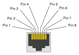
The system auto-selects the Ethernet port speed and type (duplex vs. half-duplex) when the server is booted, based on what it is connected to. Figure A-2 shows the Ethernet port.
Table A-6 shows the cable pinout assignments for the Ethernet port operating in 10/100-Base-T mode and also operating in 1000Base-T mode.
Ethernet 10/100Base-T Pinouts | Gigabit Ethernet Pinouts |
|---|---|
Pins Assignment | Pins Assignment |
1 Transmit + | 1 Transmit/Receive 0 + |
2 Transmit – | 2 Transmit/Receive 0 – |
3 Receive + | 3 Transmit/Receive 1 + |
4 NU | 4 Transmit/Receive 2 + |
5 NU | 5 Transmit/Receive 2 – |
6 Receive – | 6 Transmit/Receive 1 – |
7 NU | 7 Transmit/Receive 3 + |
8 NU | 8 Transmit/Receive 3 – |
NU = Not used
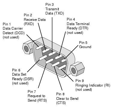
The IRU and the optional router modules have 9-pin serial interface connectors. These ports are for console interface and are capable of transferring data at rates as high as 230 kbps. Other features of the ports include the following:
Programmable data, parity, and stop bits
Programmable baud rate and modem control
Figure A-3 shows a serial port.
Table A-7 shows pinout assignments for the 9-pin male DB-9 connector.
Pin | Assignment | Description |
|---|---|---|
1 | DCD | Data carrier detect |
2 | RXD | Receive data |
3 | TXD | Transmit data |
4 | DTR | Data terminal ready |
5 | GND | Signal ground |
6 | DSR | Data set ready |
7 | RTS | Request to send |
8 | CTS | Clear to send |
9 | RI | Ring indicator |
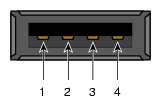
Figure A-4 shows the USB type A connector provided on the base I/O that supports general USB applications and optional keyboard and mouse configurations.
Table A-8 lists the pin assignments for the USB type A connector.
Table A-8. Pin Assignments for USB Type A Connector
Signal | Color | Pin Number |
|---|---|---|
VCC | Red | 1 |
-Data | White | 2 |
+Data | Green | 3 |
Ground | Black | 4 |


