This chapter explains how to operate your new system in the following sections:
Before operating your system, familiarize yourself with the safety information in the following sections:
| Caution: Observe all ESD precautions. Failure to do so can result in damage to the equipment. |
Wear an SGI-approved wrist strap when you handle an ESD-sensitive device to eliminate possible ESD damage to equipment. Connect the wrist strap cord directly to earth ground.
| Warning: Before operating or servicing any part of this product, read the “Safety Information” in Appendix B. |
| Warning: Keep fingers and conductive tools away from high-voltage areas. Failure to follow these precautions will result in serious injury or death. The high-voltage areas of the system are indicated with high-voltage warning labels. |
| Caution: Power off the system only after the system software has been shut down in an orderly manner. If you power off the system before you halt the operating system, data may be corrupted. |
All Altix UV 100 enclosures - known as individual rack units (IRUs) use an embedded chassis management controller (CMC) board which communicates with the blade level BMCs and other CMCs in other IRUs within the software system image (SSI). The system can also use an optional system management node (SMN) which runs top-level SGI Management Center software that can administer the entire system. In concert with the SGI management center software, they are generically known as the system control network.
The SGI Management Center System Administrator's Guide (P/N 007-5642-00x) provides information on using the optional GUI to administer your Altix UV 100 system.
The Altix UV 100 system control network provides control and monitoring functionality for each compute blade, power supply, and fan assembly in each IRU enclosure in the system.
The CMC network provides the following functionality:
Powering the entire system on and off.
Powering individual IRUs on and off.
Power on/off individual blades in an IRU.
Monitoring the environmental state of the system, including voltage levels.
Monitors and controls status LEDs on the enclosure.
Partitioning the system.
Enter controller commands to monitor or change particular system functions within a particular IRU. See the SGI UV CMC Controller Software User's Guide (P/N 007-5636-00x) for a complete list of command line interface (CLI) commands.
Provides access to the system OS console allowing you to run diagnostics and boot the system.
Provides the ability to flash system BIOS.
Access to the UV system controller network is accomplished by the following methods:
A LAN connection to the optional system management node (running the SGI Management Center software application). This can also be done using an optional VGA-connected console, see Figure 1-1.
A direct ethernet connection to a CMC, see Figure 1-2 (you must connect to ACC).
A serial connection to the “Console” port (see Figure 1-2) on the CMC.
The ethernet connection is the preferred method of accessing the system console.
Administrators can perform one of the following options for connectivity:
If an optional SMN is plugged into the customer LAN, connect to the SMN (SSH w/ X11 Forwarding) and start the SGI Management Center remotely.
An in-rack system console can be directly connected to the optional system management node via VGA and PS2.You can then log into the SMN and perform system administration either through CLI commands or via the SGI Management Center interface. Note that the CMC erthernet connect port, (labeled ACC - see Figure 1-2) requires connecting to a network with a DHCP server if the SMN node is not used. The CMC is factory set to DHCP mode and thus has no fixed IP address and cannot be accessed until an IP address is established. If unknown, the IP address must be generated by accessing the CMC directly using a serial connection.
When no optional SMN is available, a serial connection is used to communicate directly with the CMC. This connection is typically used with small systems, or for set-up or service purposes, or for system controller and system console access where an ethernet connection or in-rack system console is not used or available.
The two primary ways to communicate with and administer the Altix UV 100 system are through the optional SGI Management Center interface or the UV command line interface (CLI).
The UV command line interface is accessible by logging into either the optional SMN or directly into a chassis management controller (CMC).
Log in as root, (default password root) when logging into the CMC.
Login as sysco, when logging into the SMN.
Once a connection to the SMN or CMC is established, system control commands can be entered.
See “Powering On and Off from the Command Line Interface” for specific examples of using the CLI commands.
The following CLI command options are available specifically for the SMN:
-h|--help This help message.
hh|--help This help message + CLI help message.
-q|--quiet No disgnostic message.
-s|--system Select UV system. If only one system is present, this one is selected.
Otherwise, this option is mandatory.
-S|--show depth Show nodes at depth >= 1 using optional supplied pattern.
Default pattern=*
-t|--target One target in one of the two following formats:
a. rack[/slot[/blade]]
b. r{1..}[{s|i}{1..2}[{b|n}{0..15}]]
| Note: This format is NOT for uvcli only. |
Examples: r1i02 = rack 1, slot 2
r2i1b4 = rack 2, slot 1, blade 4
Select the target from the CLI command itself or, if not available, using the -t option.
The following are examples of uvcli commands:
uvcli --help This help.
uvcli -- leds --help Help on leds command.
uvcli leds r1i1b4 Show leds on BMC located at rack 1, slot1, blade 4.
uvcli -t 1/1 leds Show leds on all BMC in rack 1, slot 1.
uvcli -- leds -v r1i1 Same as previous command but more verbose.
uvcli -S 1 Show all system serial numbers.
uvcli -S 1 '*/part*' Show all system partitions.
The following list of available CLI commands are specifically for the SMN:
auth authenticate SSN/APPWT change
bios perform bios actions
bmc access BMC shell
cmc access CMC shell
config show system configuration
console access system consoles
help list available commands
hel access hardware error logs
hwcfg access hardware configuration variable
leds display system LED values
log display system controller logs
power access power control/status
Type '<cmd> --help' for help on individual commands.
The SGI Management Center interface is a server monitoring and management system. The SGI Management Center provides status metrics on operational aspects for each node in a system. The interface can also be customized to meet the specific needs of individual systems.
The SGI Management Center System Administrator's Guide (P/N 007-5642-00x) provides information on using the interface to monitor and maintain your Altix UV 100 system. Also, see Chapter 2 in this guide for additional reference information on the SGI Management Center interface.
This section explains how to power on and power off individual rack units, or your entire Altix UV 100 system, as follows:
Using a system controller connection, you can power on and power off individual blades, IRUs or the entire system.
If you are using an SGI Management Center interface, you can monitor and manage your server from a remote location or local terminal. For details, see the documentation for the power management tool you are using in concert with the SGI Management Center.
The Embedded Support Partner (ESP) program enables you and your SGI system support engineer (SSE) to monitor your server remotely and resolve issues before they become problems. For details on this program, see “Using Embedded Support Partner (ESP) ”.
To prepare to power on your system, follow these steps:
Check to ensure that the power connector on the cable between the rack's power distribution units (PDUs) and the wall power-plug receptacles are securely plugged in.
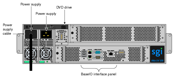
For each individual IRU that you want to power on, make sure that the power cables are plugged into both the IRU power supplies correctly, see the example in Figure 1-3. Setting the circuit breakers on the PDUs to the “On” position will apply power to the IRUs and will start the CMCs in the IRUs. Note that the CMC in each IRU stays powered on as long as there is power coming into the unit. Turn off the PDU breaker switch on the PDU(s) that supply voltage to the IRU's power supplies if you want to remove all power from the unit.
If you plan to power on a server that includes optional mass storage enclosures, make sure that the power switch on the rear of each PSU/cooling module (one or two per enclosure) is in the 1 (on) position.
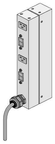
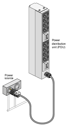
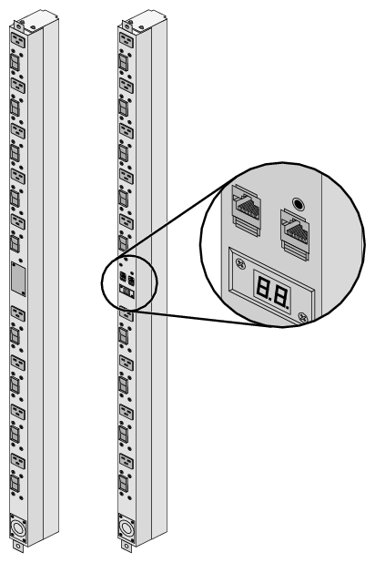
Make sure that all PDU circuit breaker switches (see the examples in the following three figures) are turned on to provide power to the server when the system is powered on.
Figure 1-4 shows an example of a single-phase 2-plug PDU that can be used with the Altix UV 100 system. This is the PDU that is used to distribute power to the IRUs when the system is configured with single-phase power.
Figure 1-5 shows an example of an eight-plug single-phase PDU that can be used in the Altix UV 100 rack system. This unit is used to support auxiliary equipment in the rack.
Figure 1-6 shows examples of the three-phase PDUs that can be used in the SGI Altix UV 100 system. These PDUs are used to distribute power to the IRUs when the system is configured with three-phase power
The Altix UV 100 command line interface is accessible by logging into either the optional system management node (SMN) as sysco or the CMC as root.
Instructions issued at the command line interface of a local console prompt typically only affect the local partition or a part of the system. Depending on the directory level you are logged in at, you may power up an entire partition (SSI), a single rack, or a single IRU enclosure. In CLI command console mode, you can obtain only limited information about the overall system configuration. An SMN has information about the IRUs in its SSI. Each IRU has information about its internal blades, and also (if other IRUs are attached via NUMAlink to the IRU) information about those IRUs.
If a system management node (SMN) is not available, it is possible to power on and administer your system directly from the CMC. When available, the optional SMN should always be the primary interface to the system.
The console type and how these console types are connected to the Altix UV 100 systems is determined by what console option is chosen. Establish either a serial connection and/or network/Ethernet connection to the CMC.
The console type and how these console types are connected to the Altix UV 100 servers is determined by what console option is chosen. If you have an Altix UV 100 server and wish to use a serially-connected “dumb terminal”, you can connect the terminal via a serial cable to the (DB-9) RS-232-style console port connector on the CMC. The terminal should be set to the following functional modes:
Baud rate of 115,200
8 data bits
One stop bit, no parity
No hardware flow control (RTS/CTS)
Note that a serial console is generally connected to the first (bottom) IRU in any single rack configuration.
If you have an Altix UV 100 system and wish to use a serially-connected "dumb terminal", you can connect the terminal via a serial cable to the (DB-9) RS-232-style console port connector on the CMC board of the IRU.
The terminal should be set to the operational modes described in the previous subsection.
Note that a serial console is generally connected to the CMC on the first (bottom) IRU in any single rack configuration.
On the system management node (SMN) port, the CMC is configured to request an IP address via dynamic host configuration protocol (DHCP).
If your system does not have an SMN, the CMC address cannot be directly obtained by DHCP and will have to be assigned, see the following subsections for more information.
For IP address configuration, there are two options: DHCP or static IP. The following subsections provide information on the setup and use of both.
Network (LAN RJ-45) connections to the Altix UV 100 CMC are always made via the ACC port.
For DHCP, you must determine the IP address that the CMC has been assigned; for a static IP, you must also configure the CMC to use the desired static IP address.
To use the serial port connection, you must attach and properly configure an RS-232 cable to the CMC's "CONSOLE" port. Configure the serial port as described in “Serial Console Hardware Requirements”.
When the serial port session is established, the console will show a CMC login, and the user can login to the CMC as user "root" with password "root".
To obtain and use a DHCP generated IP address, plug the CMC's external network port (ACC) into a network that provides IP addresses via DHCP, the CMC can then acquire an IP address.
To determine the IP address assigned to the CMC, you must first establish a connection to the CMC serial port (as indicated in the section “Serial Console Hardware Requirements”), and run the command "ifconfig eth0". This will report the IP address that the CMC is configured to use.
Running the CMC with DHCP is not recommended as the preferred option for Altix UV 100 systems. The nature of DHCP makes it difficult to determine the IP address of the CMC, and it is possible for that IP address to change over time, depending on the DHCP configuration usage. The exception would be a configuration where the system administrator is using DHCP to assign a "permanent" IP address to the CMC.
To switch from a static IP back to DHCP, the configuration file /etc/sysconfig/ifcfg-eth0 on the CMC must be modified (see additional instructions in the “Using a Static IP Address” section). The file must contain the following line to enable use of DHCP:
BOOTPROTO=dhcp |
To configure the CMC to use a static IP address, the user/administrator must edit the configuration file /etc/sysconfig/ifcfg-eth0 on the CMC. The user can use the "vi" command
(i.e. "vi /etc/sysconfig/ifcfg-eth0") to modify the file.
The configuration file should be modified to contain these lines:
BOOTPROTO=static IPADDR=<IP address to use> NETMASK=<netmask> GATEWAY=<network gateway IP address> HOSTNAME=<hostname to use> |
Note that the "GATEWAY" and "HOSTNAME" lines are optional.
After modifying the file, save and write it using the vi command ":w!", and then exit vi using ":q". Then reboot the CMC (using the "reboot" command); after it reboots, it will be configured with the specified IP address.
You can use a network connection to power on your UV system as described in the following steps:
Establish a Network/Ethernet connection (as detailed in the previous subsections). CMCs have their rack and “U” position set at the factory. The CMC will have an IP address, similar to the following:
ACC 172.17.<rack>.<slot>
You can use the IP address of the CMC to login, as follows:
ssh root@<IP-ADDRESS>
Typically, the default password for the CMC set out of the SGI factory is root. The default password for logging in as sysco on the SMN is sgisgi.
The following example shows the CMC prompt:
SGI Chassis Manager Controller, Firmware Rev. 0.x.xx
CMC:r1i1c>
This refers to rack 1, IRU 1, CMC.
Power up your Altix UV system using the power on command, as follows:
CMC:r1i1c> power on
The system will take time to fully power up (depending on size and options). Larger systems take longer to fully power on. Information on booting Linux from the shell prompt is included at the end of the next subsection (“Monitoring Power On”).
| Note: The commands are the same from the CMC or SMN command line interface. |
The following command options can be used with either the CMC or SMN CLI:
usage: power [-vcow] on|up [TARGET]...turns power on
-v, --verbose verbose output
-c, --clear clear EFI variables (system and partition targets only)
-o, --override override partition check
-w, --watch watch boot progress
To monitor the power-on sequence during boot, see the next section “Monitoring Power On”, the -uvpower option must be included.
Establish another connection to the SMN or CMC and use the uvcon command to open a system console and monitor the system boot process. Use the following steps:
CMC:r1i1c> uvcon
uvcon: attempting connection to localhost... uvcon: connection to SMN/CMC (localhost) established. uvcon: requesting baseio console access at r001i01b00... uvcon: tty mode enabled, use 'CTRL-]' 'q' to exit uvcon: console access established uvcon: CMC <--> BASEIO connection active ************************************************ ******* START OF CACHED CONSOLE OUTPUT ******* ************************************************ ******** [20100512.143541] BMC r001i01b10: Cold Reset via NL broadcast reset ******** [20100512.143541] BMC r001i01b07: Cold Reset via NL broadcast reset ******** [20100512.143540] BMC r001i01b08: Cold Reset via NL broadcast reset ******** [20100512.143540] BMC r001i01b12: Cold Reset via NL broadcast reset ******** [20100512.143541] BMC r001i01b14: Cold Reset via NL broadcast reset ******** [20100512.143541] BMC r001i01b04: Cold Reset via NL.... |
| Note: Use CTRL-] q to exit the console. |
Depending upon the size of your system, in can take 5 to 10 minutes for the Altix UV system to boot to the EFI shell. When the shell> prompt appears, enter fs0, as follows:
shell> fs0
At the fs0 prompt, enter the Linux boot loader information, as follows:
fs0> /efi/suse/elilo
The ELILO Linux Boot loader is called and various SGI configuration scripts are run and the SUSE Linux Enterprise Server 11 Service Pack x installation program appears.
To power down the Altix UV system, use the power off command, as follows:
CMC:r1i1c> power off ==== r001i01c (PRI) ==== |
You can also use the power status command, to check the power status of your system
CMC:r1i1c> power status ==== r001i01c (PRI) ==== |
on: 0, off: 32, unknown: 0, disabled: 0
Commands issued from the SGI Management Center interface are typically sent to all enclosures and blades in the system (up to a maximum 768 compute cores) depending on set parameters. SGI Management Center services are started and stopped from scripts that exist in
/etc/init.d
SGI Management Center, is commonly installed in /opt/sgi/sgimc, and is controlled by one of these services—this allows you to manage SGI Management Center services using standard Linux tools such as chkconfig and service.
If your SGI Management Center interface is not already running, or you are bringing it up for the first time, use the following steps:
Open an ssh or other terminal session command line console to the SMN using a remote workstation or local VGA terminal.
Use the information in the section “Preparing to Power On” to ensure that all system components are supplied with power and ready for bring up.
Log in to the SMN command line as root (the default password is sgisgi).
On the command line, enter mgrclient and press Enter. The SGI Management Center Login dialog box is displayed.
Enter a user name (root by default) and password (root by default) and click OK.
The SGI Management Center interface is displayed.The power on (green button) and power off (red button) are located in the middle of the SGI Management Center GUI's Tool Bar - icons which provide quick access to common tasks and features.
See the SGI Management Center System Administrator's Guide for more information.
Embedded Support Partner (ESP) automatically detects system conditions that indicate potential future problems and then notifies the appropriate personnel. This enables you and SGI system support engineers (SSEs) to proactively support systems and resolve issues before they develop into actual failures.
ESP enables users to monitor one or more systems at a site from a local or remote connection. ESP can perform the following functions:
Monitor the system configuration, events, performance, and availability.
Notify SSEs when specific events occur.
Generate reports.
ESP also supports the following:
Remote support and on-site troubleshooting.
System group management, which enables you to manage an entire group of systems from a single system.
For additional information on this and other available monitoring services, see the section “SGI Electronic Support” in Chapter 6.
You can monitor and interact with your Altix UV 100 server from the following sources:
Using the SGI 1U rackmount console option you can connect directly to the optional system management node (SMN) for basic monitoring and administration of the Altix system. See “1U Console Option” for more information; SLES 11 or later is required.
A PC or workstation on the local area network can connect to the optional SMN's external ethernet port and set up remote console sessions or display GUI objects from the SGI Management Center interface.
A serial console display can be plugged into the CMC at the rear of IRU 001. You can also monitor IRU information and system operational status from other IRUs that are connected to IRU 001.
These console connections enable you to view the status and error messages generated by the chassis management controllers in your Altix UV 100 rack. For example, you can monitor error messages that warn of power or temperature values that are out of tolerance. See the section “Console Hardware Requirements” in Chapter 2, for additional information.
Besides adding a network-connected system console or basic VGA monitor, you can add or replace the following hardware items on your Altix UV 100 series server:
Peripheral component interface (PCIe) cards into the optional PCIe expansion chassis.
PCIe cards installed or replaced in a two-slot internal PCIe riser card.
Disk or DVD drives in your Altix UV 100 IRU drive tray.
The PCIe based I/O sub-systems, are industry standard for connecting peripherals, storage, and graphics to a processor blade. The following are the primary configurable I/O system interfaces for the Altix UV 100 series systems:
The optional two-slot internal PCIe riser card is a compute blade-installed riser card that supports one x8 and one x16 PCIe Gen2 cards.
The optional external PCIe riser card is a compute blade-installed riser card that supports two x16 PCI express Gen2 ports. These ports can be used to connect to an optional I/O expansion chassis that supports multiple PCIe cards. Each x16 connector on the riser card can support one I/O expansion chassis.

Important: PCIe cards installed in a two-slot internal PCIe riser card are not hot swappable or hot pluggable. The compute blade using the PCIe riser must be powered down and removed from the system before installation or removal of a PCIe card. See also, “Installing Cards in the 1U PCIe Expansion Chassis” for more information on PCIe options.
Not all blades or PCIe cards may be available with your system configuration. Check with your SGI sales or service representative for availability. See Chapter 5, “PCIe and Disk Add or Replace Procedures” for detailed instructions on installing or removing PCIe cards or Altix UV 100 system disk drives.


