This chapter describes the general interaction and functions of the overall Altix UV 100 system control. System control parameters depend somewhat on the overall size and complexity of the SGI Altix UV 100 but will generally include the following three areas:
The optional system management node (SMN) which runs the SGI Management Center software
The chassis management controllers (CMC) boards - one in each IRU
The individual blade-based board management controllers (BMCs) - report to the CMCs

Note: It is possible to operate and administer a very basic (single-rack) SGI Altix UV 100 system without using an optional SMN and the SGI Management Center. Use of an SMN will enhance the overall system control process and is highly recommended for multi-rack systems.
The system control network configuration of your server will depend on the size of the system and control options selected. Typically, an Ethernet LAN connection to the system controller network is used. This Ethernet connection is made from a local or remote PC, VGA terminal or workstation connected to the optional system management node (SMN).
The SMN is a separate stand-alone server installed in the SGI Altix UV 100 rack. The SMN acts as a gateway and buffer between the UV system control network and any other public or private local area networks as well as the system CMCs.
| Important: The SGI Altix UV system control network is a private, closed network. It should not be reconfigured in any way to change it from the standard SGI Altix UV factory installation. It should not be directly connected to any other network. The Altix UV system control network is not designed for and does not accommodate additional network traffic, routing, address naming (other than its own schema), or DCHP controls (other than its own configuration). The Altix UV system control network also is not security hardened, nor is it tolerant of heavy network traffic, and is vulnerable to Denial of Service attacks. |
An Ethernet connection directly from the SMN (Figure 2-1) to a local private or public LAN allows the system to be administered directly from a local or remote console via the SGI Management Center interface (most often installed on the SMN). Note that there is no direct inter-connected system controller function in the optional expansion PCIe modules.
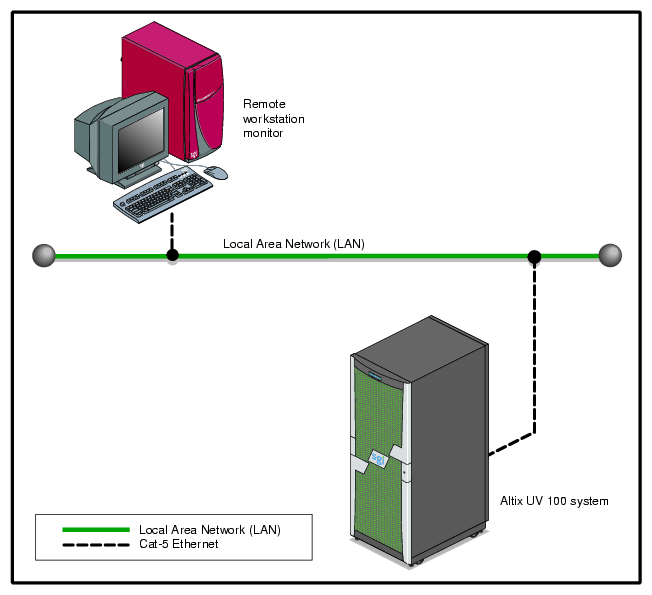
The system controller network is designed into all IRUs. Controllers within the system report and share status information via the CMC Ethernet interconnect cables. This maintains controller configuration and topology information between all controllers in an SSI. Figure 2-2 shows an example system control network using an optional and separate (remote) workstation to monitor a single-rack SGI Altix UV 100 system. It is also possible to connect an optional PC or console directly to the SMN, see Figure 2-1.
| Note: Mass storage option enclosures are not specifically monitored by the system controller network. Most optional mass storage enclosures have their own internal microcontrollers for monitoring and controlling all elements of the disk array. See the owner's guide for your mass storage option for more information on this topic. |
For information on administering network connected SGI systems using the SGI Management Center, see the SGI Management Center System Administrator's Guide (P/N 007-5642-00x).
The CMC system for the SGI Altix UV 100 servers manages power control and sequencing, provides environmental control and monitoring, initiates system resets, stores identification and configuration information, and provides console/diagnostic and scan interface.
Viewing the system from the rear, the CMC blade is near the center of the IRU. The CMC accepts direction from the SMN and supports powering-up and powering-down individual or groups of compute blades and environmental monitoring of all units within the IRU. The CMC sends operational requests to the Baseboard Management Controller (BMC) on each compute/memory blade installed. The CMC provides data collected from the compute nodes within the IRU to the SMN upon request. Each CMC in a system communicates with other CMCs and the optional SMN via a private system control ethernet network.
CMCs can communicate with the blade BMCs and other IRU CMCs when they are linked together under a single system image (SSI); also called a partition. Each CMC shares its information with an optional SMN and other CMCs within the SSI. Note that the optional SMN (server), optional mass storage units and PCIe expansion enclosures do not have a CMC installed.
Each compute blade in an IRU has a baseboard management controller (BMC). The BMC is a built-in specialized microcontroller hardware component that monitors and reports on the functional “health” status of the blade. The BMC provides a key functional element in the overall Intelligent Platform Management Interface (IPMI) architecture.
The BMC acts as an interface to the higher levels of system control such as the IRU's CMC boards and the higher level control system used in the optional system management node. The BMC can report any on-board sensor information that it has regarding temperatures, power status, operating system condition and other functional parameters that may be reported by the blade.When any of the preset limits fall out of bounds, the information will be reported by the BMC and an administrator can take some corrective action. This could entail a node shutdown, reset (NMI) or power cycling of the individual blade.
The individual blade BMCs do not have information on the status of other blades within the IRU. This function is handled by the CMCs and/or the optional SMN. Note that blades equipped with an optional BaseIO riser board have a dedicated BMC Ethernet port.
In all Altix UV 100 servers all the system controller types (SMNs, CMCs and BMCs) communicate with each other in the following ways:
System control commands and communications are passed between the SMN and CMCs via a private dedicated gigabit ethernet. The CMCs communicate directly with the BMC in each installed blade by way of the IRU's internal backplane.
All the primary CMCs can communicate with each other via an ethernet “ring” configuration network.
All IRUs have one CMC board installed. The following subsections describe the basic features of the controllers:
| Note: For additional information on controller commands, see the SGI UV CMC Controller Software User's Guide (P/N 007-5636-00x). |
The following list summarizes the control and monitoring functions that the CMC performs. Many of the controller functions are common across all IRUs, however, some functions are specific to the type of enclosure.
Controls voltage margining within the IRU
Monitors individual blade status via blade BMCs
Controls and monitors IRU fan speeds
Reads system identification (ID) PROMs
Monitors voltage levels and reports failures
Monitors and controls warning LEDs
Monitors the On/Off power cycles
Monitors the power status of the IRU
The console type and how these console types are connected to the Altix UV 100 servers is determined by what console option is chosen.
If you have an Altix UV 100 server and wish to use a serially-connected “dumb terminal”, you can connect the terminal via a serial cable to the (DB-9) RS-232-style console port connector on the CMC.
The terminal should be set to the following functional modes:
Baud rate of 115,200
8 data bits
One stop bit, no parity
No hardware flow control (RTS/CTS)
Note that a serial console is generally connected to the first (bottom) IRU in any single rack configuration.
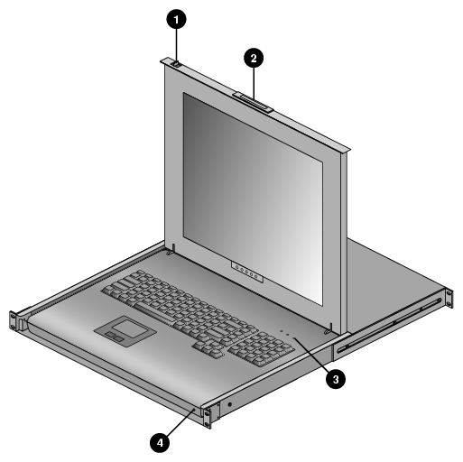
The SGI optional 1U console is a rackmountable unit that includes a built-in keyboard/touchpad, and uses a 17-inch (43-cm) LCD flat panel display of up to 1280 x 1024 pixels.
The 1U flat panel console option has the following listed features:
Slide Release - Move this tab sideways to slide the console out. It locks the drawer closed when the console is not in use and prevents it from accidentally sliding open.
Handle - Used to push and pull the module in and out of the rack.
LCD Display Controls - The LCD controls include On/Off buttons and buttons to control the position and picture settings of the LCD display.
Power LED - Illuminates blue when the unit is receiving power.
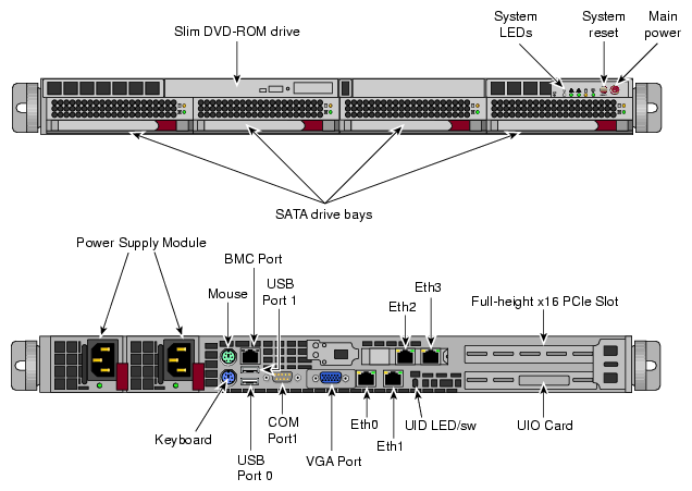
The 1U console attaches to the optional system management node server using PS/2 and HD15M connectors or to an optional KVM switch (not provided by SGI). See Figure 2-4 for the SMN video connection points. The 1U console is basically a “dumb” VGA terminal, it cannot be used as a workstation or loaded with any system administration program.
The 27-pound (12.27-kg) console automatically goes into sleep mode when the cover is closed.


