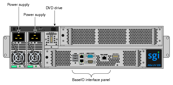
This chapter provides an overview of the physical and architectural aspects of your SGI Altix UV 100 series system. The major components of the Altix UV 100 series systems are described and illustrated.
The Altix UV 100 series is a family of multiprocessor distributed shared memory (DSM) computer systems that initially scale from 16 to 768 Intel processor cores as a cache-coherent single system image (SSI). Future releases may scale to larger processor counts for single system image (SSI) applications. Contact your SGI sales or service representative for the most current information on this topic.
In a DSM system, each processor board contains memory that it shares with the other processors in the system. Because the DSM system is modular, it combines the advantages of lower entry-level cost with global scalability in processors, memory, and I/O. You can install and operate the Altix UV 100 series system in your lab or server room. Each 42U SGI rack holds up to twelve 3U high enclosures that each support one or two compute/memory and I/O sub modules known as “blades.” These blades are single printed circuit boards (PCBs) with ASICS, processors, memory components and I/O chip sets mounted on a mechanical carrier. The blades slide directly in and out of the Altix UV 100 IRU enclosures.
This chapter consists of the following sections:
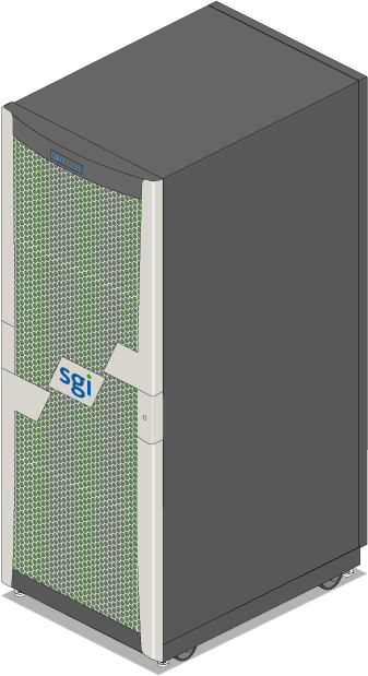
Figure 3-1 shows the front view of a single-rack Altix UV 100 system.
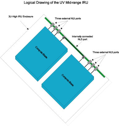
The basic enclosure within the Altix UV 100 system is the 3U high “individual rack unit” (IRU). The IRU enclosure contains one or two blades connected to each other via NUMAlink with a maximum bi-directional bandwidth communication rate of up to 15 GB/sec.
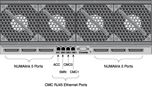
Each IRU has ports that are brought out to external NUMAlink 5 connectors located on the back of each IRU. The 20U, 40U or 42U rack for this server houses all IRU enclosures, option modules, and other components; up to (480 processor cores) in a single rack. The Altix UV 100 server system can expand up to 768 Intel processor cores per SSI; a minimum of one BaseIO riser equipped blade is required for every 768 processor cores. Higher core counts in an SSI may be available in future releases, check with your SGI sales or service representative for current information.
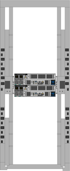
Figure 3-2 shows an example of how IRU placement is done in a single-rack Altix UV 100 server.
The system requires a minimum of one rack with enough power distribution units (PDUs) to support the IRUs and any optional equipment installed in the rack. Each single-phase PDU has two or eight outlets (one PDU is required to support up to two IRUs and two power connections are needed for the optional SMN).
The three-phase PDU has 9 outlets used to support the IRUs and any optional equipment that may be installed in a rack.
You can also add additional PCIe expansion cards or RAID and non-RAID disk storage to your server system.
The Altix UV 100 computer system is based on a distributed shared memory (DSM) architecture. The system uses a global-address-space, cache-coherent multiprocessor that scales up to 480 processor cores in a single rack. Because it is modular, the DSM combines the advantages of lower entry cost with the ability to scale processors, memory, and I/O independently to a maximum of 768 cores on a single-system image (SSI). Larger SSI configurations may be offered in the future, contact your SGI sales or service representative for information.
The system architecture for the Altix UV 100 system is a fifth-generation NUMAflex DSM architecture known as NUMAlink 5. In the NUMAlink 5 architecture, all processors and memory can be tied together into a single logical system. This combination of processors, memory, and internal switches constitute the interconnect fabric called NUMAlink within each IRU enclosure.
The basic expansion building block for the NUMAlink interconnect is the processor node; each processor node consists of a Hub ASIC and two six-core, eight-core or ten-core processors with on-chip secondary caches. The Intel processors are connected to the Hub ASIC via quick path interconnects.
The Hub ASIC is the heart of the processor and memory node blade technology. This specialized ASIC acts as a crossbar between the processors, local SDRAM memory, and the network interface. The Hub ASIC enables any processor in the SSI to access the memory of all processors in the SSI.
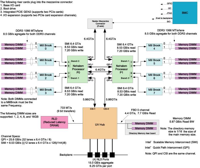
Figure 3-3 shows a functional block diagram of the Altix UV 100 series system IRU processor blades.
The main features of the Altix UV 100 series server systems are discussed in the following sections:
The Altix UV 100 series systems are modular systems. The components are primarily housed in building blocks referred to as individual rack units (IRUs). Additional optional mass storage may be added to the rack along with additional IRUs. You can add different types of blade options to a system IRU to achieve the desired system configuration. You can easily configure systems around processing capability, I/O capability, memory size, or storage capacity. The air-cooled IRU enclosure system has redundant, hot-swap fans and redundant, hot-swap power supplies.
In the Altix UV 100 series server, memory is physically distributed both within and among the IRU enclosures (compute/memory/I/O blades); however, it is accessible to and shared by all NUMAlinked devices within the single-system image (SSI). This means all NUMAlinked components sharing a single Linux operating system, operate and share the memory “fabric” of the system. Memory latency is the amount of time required for a processor to retrieve data from memory. Memory latency is lowest when a processor accesses local memory. Note the following sub-types of memory within a system:
If a processor accesses memory that it is connected to on a compute node blade, the memory is referred to as the node's local memory. Figure 3-4 shows a conceptual block diagram of the blade's memory, compute and I/O pathways.
If processors access memory located in other blade nodes within the IRU, (or other NUMAlinked IRUs) the memory is referred to as remote memory.
The total memory within the NUMAlinked system is referred to as global memory.
Like DSM, I/O devices are distributed among the blade nodes within the IRUs. Each BaseIO riser card equipped blade node is accessible by all compute nodes within the SSI (partition) through the NUMAlink interconnect fabric.
Each IRU has a chassis management controller (CMC) located directly below the upper set of cooling fans in the rear of the IRU. The chassis manager supports powering up and down of the compute blades and environmental monitoring of all units within the IRU.
One GigE port from each compute blade connects to the CMC blade via the internal IRU backplane. A second GigE port from each blade slot is also connected to the CMC. This second port is used to support an optional BaseIO riser card.
As the name implies, the cache-coherent non-uniform memory access (ccNUMA) architecture has two parts, cache coherency and nonuniform memory access, which are discussed in the sections that follow.
The Altix UV 100 server series use caches to reduce memory latency. Although data exists in local or remote memory, copies of the data can exist in various processor caches throughout the system. Cache coherency keeps the cached copies consistent.
To keep the copies consistent, the ccNUMA architecture uses directory-based coherence protocol. In directory-based coherence protocol, each block of memory (128 bytes) has an entry in a table that is referred to as a directory. Like the blocks of memory that they represent, the directories are distributed among the compute/memory blade nodes. A block of memory is also referred to as a cache line.
Each directory entry indicates the state of the memory block that it represents. For example, when the block is not cached, it is in an unowned state. When only one processor has a copy of the memory block, it is in an exclusive state. And when more than one processor has a copy of the block, it is in a shared state; a bit vector indicates which caches may contain a copy.
When a processor modifies a block of data, the processors that have the same block of data in their caches must be notified of the modification. The Altix UV 100 server series uses an invalidation method to maintain cache coherence. The invalidation method purges all unmodified copies of the block of data, and the processor that wants to modify the block receives exclusive ownership of the block.
The Altix UV 100 server series components have the following features to increase the reliability, availability, and serviceability (RAS) of the systems.
Power and cooling:
IRU power supplies are redundant and can be hot-swapped under most circumstances.
IRUs have overcurrent protection at the blade and power supply level.
Fans are redundant and can be hot-swapped.
Fans run at multiple speeds in the IRUs. Speed increases automatically when temperature increases or when a single fan fails.
System monitoring:
System controllers monitor the internal power and temperature of the IRUs, and can automatically shut down an enclosure to prevent overheating.
All main memory has Intel Single Device Data Correction, to detect and correct 8 contiguous bits failing in a memory device. Additionally, the main memory can detect and correct any two-bit errors coming from two memory devices (8 bits or more apart).
All high speed links including Intel Quick Path Interconnect (QPI), Intel Scalable Memory Interconnect (SMI), and PCIe have CRC check and retry.
The NUMAlink interconnect network is protected by cyclic redundancy check (CRC).
Each blade/node installed has status LEDs that indicate the blade's operational condition; LEDs are readable at the front of the IRU.
Systems support the optional Embedded Support Partner (ESP), a tool that monitors the system; when a condition occurs that may cause a failure, ESP notifies the appropriate SGI personnel.
Systems support optional remote console and maintenance activities.
Power-on and boot:
Automatic testing occurs after you power on the system. (These power-on self-tests or POSTs are also referred to as power-on diagnostics or PODs).
Processors and memory are automatically de-allocated when a self-test failure occurs.
Boot times are minimized.
Further RAS features:
Systems have a local field-replaceable unit (FRU) analyzer.
All system faults are logged in files.
Memory can be scrubbed using error checking code (ECC) when a single-bit error occurs.
The Altix UV 100 series system features the following major components:
20U, 40U or 42U rack. These racks are used for both the compute and I/O rack in the Altix UV 100 system. Up to 12 IRUs can be installed in each rack (six in the 20U rack). There is also space reserved for an optional system management node and other optional 1U components such as a PCIe expansion enclosure.
Individual Rack Unit (IRU). This 3U high enclosure contains two power supplies, one or two compute/memory blades, BaseIO and other optional riser enabled blades for the Altix UV 100. Figure 3-5 shows the Altix UV 100 IRU front components.
Compute blade. Holds two processor sockets and 8 or 16 memory DIMMs. Each compute blade can be ordered with a riser card that enables the blade to support various I/O options.
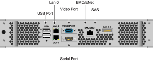
BaseIO enabled compute blade. I/O riser enabled blade that supports all base system I/O functions including two ethernet connectors, one SAS port, one BMC ethernet port and three USB ports. Figure 3-6 shows the front components of the I/O riser enables blade.
Drives. Each IRU has a drive tray that supports one optional DVD drive and three or four hard disk drives. Installing the DVD drive limits the tray to supporting three hard disks.
Two-Slot Internal PCIe enabled compute blade. The internal PCIe riser based compute blade supports two internally installed PCI Express option cards.
External PCIe enabled compute blade. This riser enabled board must be used in conjunction with a PCIe expansion enclosure. A x16 adapter card connects from the blade to the expansion enclosure, supporting up to four PCIe option cards.

Note: PCIe card options may be limited, check with your SGI sales or support representative. CMC and external NUMAlink Connectors. The CMC and external NUMAlink connectors are located on the rear of each IRU below the unit's fans (see Figure 3-7).
Bays in the racks are numbered using standard units. A standard unit (SU) or unit (U) is equal to 1.75 inches (4.445 cm). Because IRUs occupy multiple standard units, IRU locations within a rack are identified by the bottom unit (U) in which the IRU resides. For example, in a 42U rack, an IRU positioned in U01 through U03 is identified as U01.
Each rack is numbered with a three-digit number sequentially beginning with 001. A rack contains IRU enclosures, optional mass storage enclosures, and potentially other options. In a single compute rack system, the rack number is always 001.
Availability of optional components for the SGI Altix UV 100 systems may vary based on new product introductions or end-of-life components. Some options are listed in this manual, others may be introduced after this document goes to production status. Check with your SGI sales or support representative for current information on available product options not discussed in this manual.
