This chapter provides information about installing and removing PCIe cards and system disk drives from your SGI system, as follows:
This section describes how to open the system for maintenance and upgrade, protect the components from static damage, and return the system to operation. The following topics are covered:
“Returning the System to Operation”

Warning: To avoid problems that could void your warranty, your SGI or other approved system support engineer (SSE) should perform all the setup, addition, or replacement of parts, cabling, and service of your SGI Altix UV 100 system, with the exception of the following items that you can perform yourself: Using your system console or network access workstation to enter commands and perform system functions such as powering on and powering off, as described in this guide.
Installing, removing or replacing PCIe cards in the optional 1U PCIe expansion chassis or two-card PCIe riser blade.
Installing or replacing hard disk or DVD drives in the IRU.
Using the ESI/ops panel (operating panel) on optional mass storage.
To prepare the system for maintenance, follow these steps:
If you are logged on to the system, log out. Follow standard procedures for gracefully halting the operating system.
Go to the section “Powering the System On and Off” if you are not familiar with power down procedures.
After the system is powered off, locate the power distribution unit(s) (PDUs) in the front of the rack and turn off the circuit breaker switches on each PDU.
When you finish installing or removing components, return the system to operation as follows:
Turn each of the PDU circuit breaker switches to the “on” position.
Power up the system. If you are not familiar with the proper power-on procedure, review the section “Powering the System On and Off”.
Verify that the LEDs on the system power supplies and system blades turn on and illuminate green which indicates that the power-on procedure is proceeding properly.
If your system does not boot correctly, see “Troubleshooting Chart” in Chapter 6, for troubleshooting procedures.
This section provides a brief overview of the PCI Express (PCIe) technology available as an option with your system. PCI Express has both compatibility and differences with older PCI/PCI-X technology. Check with your SGI sales or service representative for more detail on specific PCI Express board options available with the SGI Altix UV 100.
PCI Express is compatible with PCI/PCI-X in the following ways:
Compatible software layers
Compatible device driver models
Same basic board form factors
PCIe controlled devices appear the same as PCI/PCI-X devices to most software
PCI Express technology is different from PCI/PCI-X in the following ways:
PCI Express uses a point-to-point serial interface vs. a shared parallel bus interface used in older PCI/PCI-X technology
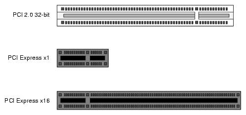
PCIe hardware connectors are not compatible with PCI/PCI-X, (see Figure 5-1)
Potential sustained throughput of x16 PCI Express is approximately four times that of the fastest PCI-X throughputs
PCI Express technology uses two pairs of wires for each transmit and receive connection (4 wires total). These four wires are generally referred to as a lane or x1 connection - also called “by 1”. SGI Altix UV 100 PCIe technology is available up to a x16 connector (64 wires) or “by 16” in PCI Express card slots. This technology will support PCIe boards that use connectors up to x16 in size. Table 5-1 shows this concept.
For information on which slots in the PCIe expansion chassis support what lane levels, see Table 5-2.
Table 5-1. SGI Altix UV 100 PCIe Support Levels
SGI x16 PCIe Connectors | Support levels in optional four card chassis |
|---|---|
x1 PCIe cards | Supported in all four slots |
x2 PCIe cards | Supported in all four slots |
x4 PCIe cards | Supported in all four slots |
x8 PCIe cards | Supported in two slots |
x16 PCIe cards | 1 slot supported |
x32 PCIe cards | Not supported |
| Warning: Before installing, operating, or servicing any part of this product, read the “Safety Information”. |
This section provides instructions for adding or replacing a PCIe card in a PCIe expansion enclosure installed in your system. To maximize the operating efficiency of your cards, be sure to read all the introductory matter before beginning the installation.
| Caution: To protect the PCIe cards from ESD damage, SGI recommends that you use a grounding wrist strap while installing a PCIe card. |
The PCIe expansion chassis functions in a similar manner to a computer chassis that supports PCIe slots. Always follow the manufacturer's instructions or restrictions for installing their card.
| Important: Replacement (swapping) of a PCIe card in the 1U chassis may be done while the system is powered on. Addition of a new card while the system is running requires a reboot to initiate recognition and functionality. Removal (without replacement) of an existing PCIe card may cause system error messages. When installing PCIe cards, ensure that the input current rating specified on the AC input label is not exceeded. |
The EB4-1U-SGI optional PCIe chassis provides space for up to four PCIe cards (see Table 5-2) in the following “lane” bandwidth configurations:
Table 5-2. PCIe Expansion Slot Bandwidth Support Levels
PCIe expansion enclosure slot # | PCIe connector level supported by slot | PCIe slot number location in board “carriage” |
|---|---|---|
Slot 1 | Up to x16 | Bottom-left side |
Slot 2 | Up to x4 | Top-left side |
Slot 3 | Up to x8 | Top-right side |
Slot 4 | Up to x4 | Bottom-right side |
| Note: Before installing the PCIe expansion cards, be sure to remove each respective slot cover and use its screw to secure your expansion card in place. |
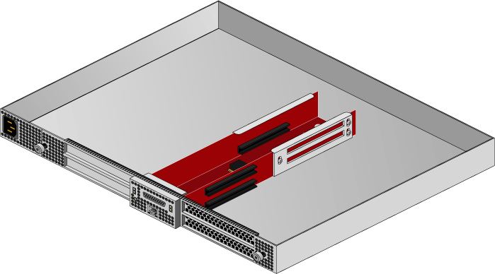
Working from the front of the expansion chassis, locate the two “thumb screws” that hold the PCIe board “carriage” in the expansion chassis, see Figure 5-2.
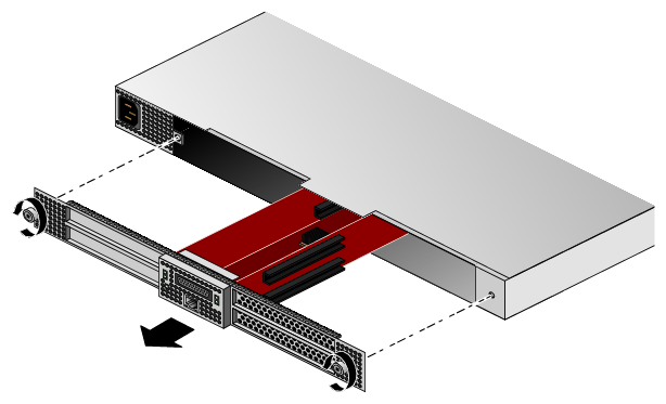
Turn the two thumb screws counter-clockwise until they disengage from the 1U chassis.
Pull the T-shaped board “carriage” out of the chassis until the slots are clear of the unit, see Figure 5-3 for an example.
Select an available slot based on the lane support your PCIe card requires, see Table 5-2.
Remove the metal slot cover from the selected slot and retain its screw.
Fit the PCIe card into the slot connector with the connector(s) extending out the front of the bracket, then secure the board with the screw that previously held the metal slot cover.
Push the PCIe board “carriage” back into the enclosure until it is seated and twist the retaining thumb screws clockwise (right) until fully secure.

Important: After installation of a new card, be sure to power on the PCIe expansion enclosure before re-booting your system.
If your system is equipped with an optional PCIe riser blade, you can install or replace PCIe cards (up to x16) using the following steps and illustrations:
Obtain a T10 torx driver to perform the necessary disassembly of the blade. It is recommended that you use an anti-static wrist strap during this procedure.
Shut down the system or the individual blade you will be upgrading and open the front door of the rack.
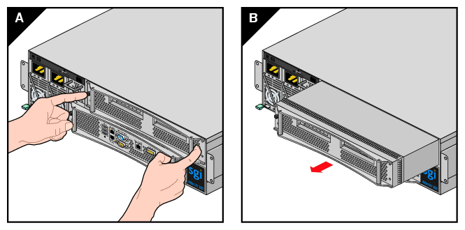
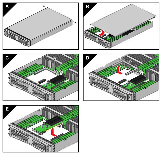
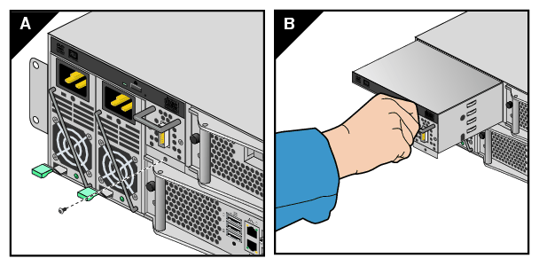
Grasp the front pull bars and depress the black release button on the blade and pull it out of the IRU, see the example in Figure 5-4. Place it on a flat static-safe working surface.
Unscrew and remove the two T10 torx-head screws located on either side of the rear part of the blade's sheetmetal housing, (see Figure 5-5). Set the screws aside for the re-installation process.
Slide the blade's sheetmetal cover back slightly and then lift it away from the unit.
Near the front of the blade you will remove a single T10 torx-head screw from the C-shaped bracket that holds both of the optional PCIe cards in place on the blade's riser board. Set the screw aside for the reinstallation process.
If you are replacing a PCIe card, gently remove the existing board from the PCIe connector on the riser and place in static safe bag or container.
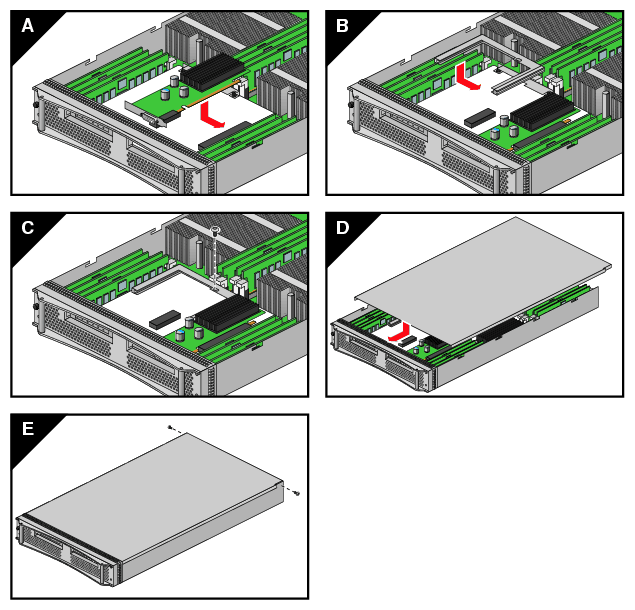
Install a new PCIe card by aligning the board's interface connector with the riser's and inserting until the card is flush to the connector, see Figure 5-6. The PCIe functional connector(s) such as graphics, Fibre Channel, etc. should protrude from the front of the blade.
Re-secure the C-shaped bracket that holds the PCIe option cards in place on the blade's riser.
Replace the blade's sheetmetal top cover and securing screws.
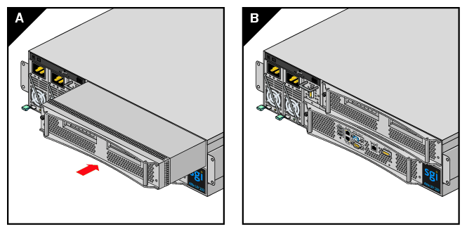
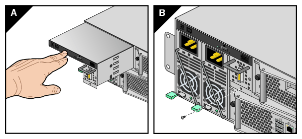
Slide the blade back into the IRU and restart the system or blade, see Figure 5-7 for an example.
The Altix UV 100 IRU holds up to four hard disk drives or one optional DVD and three hard drives in a tray. The drive tray is located in the upper left-hand corner of the IRU above the system power supplies, see Figure 5-8. The drive-tray interface cabling supports four devices total. You can operate the DVD and three hard drives at the same time. Optionally - you can operate four hard disk drives in the enclosure drive tray if you are not using a DVD drive.
Each hard disk drive in the Altix UV 100 IRU drive tray is secured by four 1/4-inch (6.35 mm) locked nuts. These nuts secure the drive's “mounting bracket” to fixed screws attached to the sheet metal tray used in the IRU. You will need a 7/32-inch (5.56 mm) nut driver or adjustable wrench to remove/replace hard disk drives.
The optional DVD drive is secured to the front section of the IRU's drive tray via Torx-head screws. Use a T10 Torx driver to remove/replace the DVD's retention screws.
Use the following steps and illustrations to add or replace a hard disk drive in the Altix UV 100:
Shut down the IRU's operating system. Use the instructions in Chapter 1 of this manual if you are unfamiliar with the procedure.
Unplug both the IRU's power supplies.
Unplug the SAS drive cable from the front of the drive tray (next to the power supplies).
Undo the drive tray retention screw by inserting a T10 Torx driver into the screw hole directly below the SAS cable connection you removed in the previous step.
Remove the retention screw and set it aside, see Figure 5-9 for an example.
Grasp the handle just above the SAS connector on the tray and pull it straight out until you can place your other hand under it for support.
Continuing to support the center part of the tray, pull it fully out of the enclosure and place on a static-free working surface.
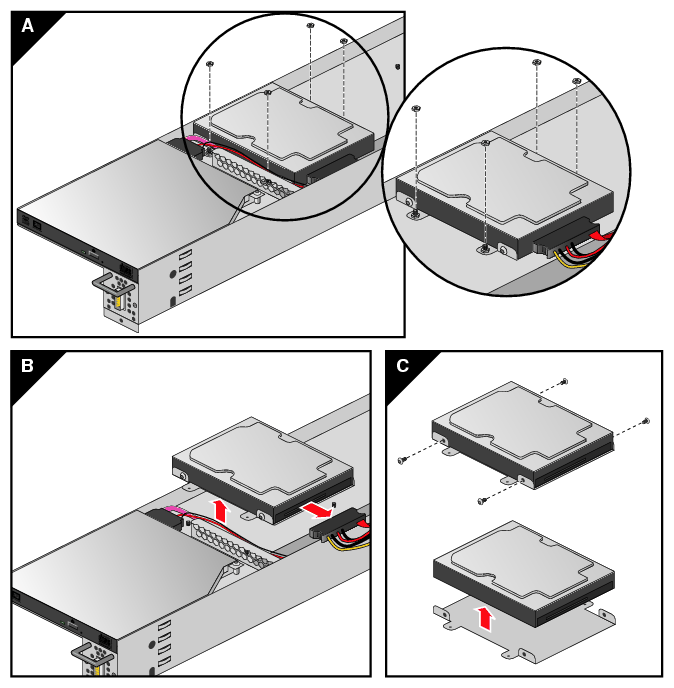
If replacing an existing hard disk drive, undo the four 7/32-inch (5.56 mm) locking nuts holding it to the drive tray; then unplug the power/data cable and extract the drive. See Figure 5-10 for an example.
Select the tray location for the new hard disk drive. If the new drive is not equipped with an Altix UV 100 style mounting bracket (sled), remove the old drive's sled and install the hardware on the replacement drive. Check with your support provider if you do not have the appropriate sled hardware to install additional drives in the tray.
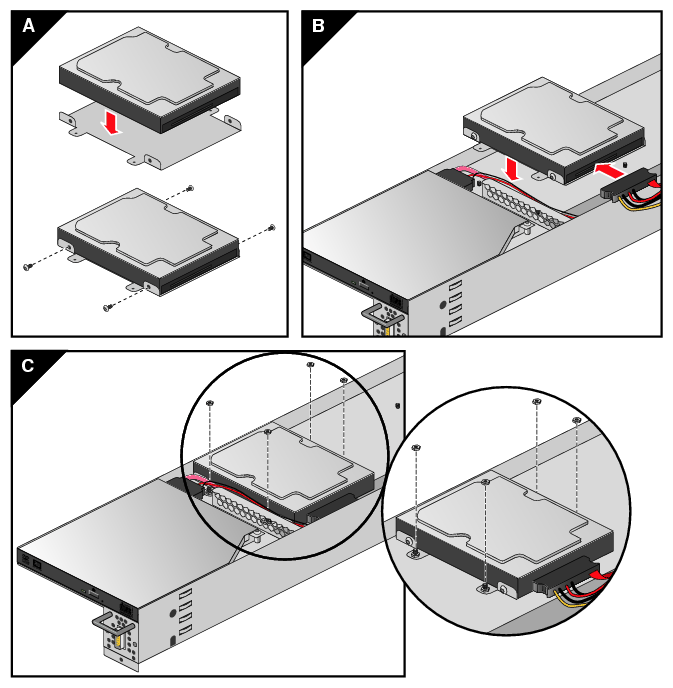
Align the four holes in the new drive's sled with the four screws on the system drive tray. Be sure that the new drive's power/data connector is facing towards the interior of the IRU where the drive interface cables are routed. See Figure 5-11 for an example.
With the new drive in place, secure it with four 7/32-inch (5.56 mm) locking nuts and attach the power/data connector.
Slide the drive tray back into position and secure it with the T10 screw removed in step 1.
Use the following steps and illustrations to install or replace a DVD drive in the IRU:
Shut down the IRU's operating system. Use the instructions in Chapter 1 of this manual if you are unfamiliar with the procedure.
Unplug both the IRU's power supplies.
Unplug the SAS drive cable from the front of the drive tray (next to the power supplies).
Undo the drive tray retention screw by inserting a T10 Torx driver into the screw hole directly below the SAS cable connection you removed in the previous step.
Remove the retention screw and set it aside.
Grasp the handle just above the SAS connector on the tray and pull it straight out until you can place your other hand under it for support.
Continuing to support the center part of the tray, pull it fully out of the enclosure and place on a static-free working surface.
Remove the two torx screws that hold the front handle on the tray, then remove the front handle. Skip the next four steps if no DVD is currently installed on the drive tray.
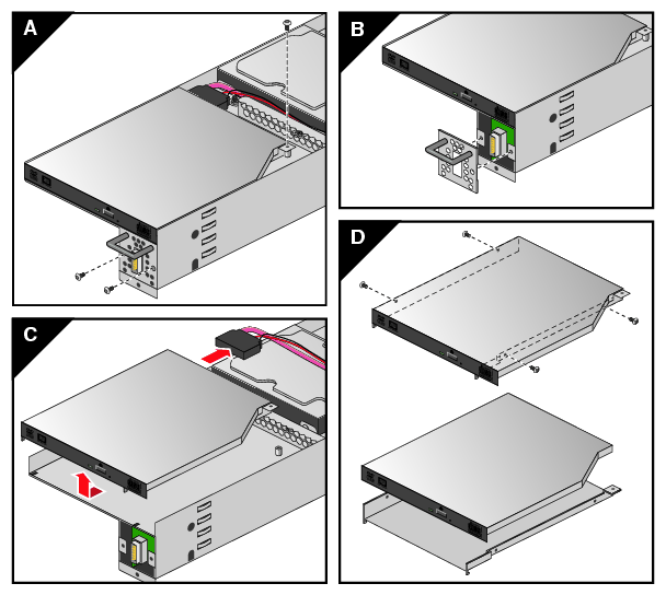
If replacing an existing DVD drive, unscrew the T10 Torx screw that holds the DVD's “L”-shaped retention bracket in place and set it aside, see Figure 5-14 for an example.
Disconnect the existing power and data cables from the failed DVD.
Pull the DVD forward and then up to free the DVD from the tray.
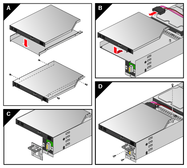
Remove the two screws from the metal brackets on the left and right sides of the DVD (four screws total). Note that the metal bracket has little hooks in the front to secure the front of the DVD to the tray.
Install the two screws from the metal brackets on the left and right sides of the new DVD (four screws total). See Figure 5-15 for an example.
Plug the DVD power and data cables into the new DVD drive and place it within the “L”-shaped bracket - the front of the drive should face the end of the drive tray.
Place the DVD back onto the tray and slide it back making sure the front hooks of the metal brackets secure the front of the DVD to the tray.
Screw the “L” bracket retention screw back into the drive tray so that the DVD is held firmly in place within the tray.
Replace the tray's front handle using the two torx screws previously removed.
Carefully slide the drive tray back into the Altix UV 100 enclosure and secure it to the enclosure with the screw removed in step 5. See Figure 5-16 for an example.
Plug the SAS cable back into the connector on the front of the drive tray.
Reconnect both of the IRU's power supplies and restart the system. Use the instructions in Chapter 1 of this manual if you are unfamiliar with the power-on procedure.
