This chapter provides the following sections to help you troubleshoot your system:
Table 6-1 lists recommended actions for problems that can occur. To solve problems that are not listed in this table, use the SGI Electronic Support system or contact your SGI system support engineer (SSE). For more information about the SGI Electronic Support system, see the “SGI Electronic Support ”.
Table 6-1. Troubleshooting Chart
Recommended Action | |
|---|---|
The system will not power on. | Ensure that the power cords of the IRU are seated properly in the power receptacles. Ensure that the PDU circuit breakers are on and properly connected to the wall source. If the power cord is plugged in and the circuit breaker is on, contact your SSE. |
An individual IRU will not power on. | Ensure the power cables of the IRU are plugged in. Confirm the PDU(s) supporting the IRU are on. |
The system will not boot the operating system. | Contact your SSE. |
An amber LED illuminates on a blade. | See Table 6-2 for a description of the status message. |
The amber (yellow) status LED of a power supply is lit or the LED is not lit at all. See Table 6-2 . | Ensure the power cable to the supply is firmly connected at both ends and that the PDU is turned to on. Check and confirm the supply is fully plugged into it's slot. If the green LED does not light, contact your support engineer. |
The PWR LED of a populated PCIe slot is not illuminated. | Reseat the PCI card. |
The Fault LED of a populated PCIe slot is illuminated (on). | Reseat the card. If the fault LED remains on, replace the card. |
The amber LED of a disk drive is on. | Replace the disk drive. |
There are a number of LEDs on the front of the IRUs that can help you detect, identify and potentially correct functional interruptions in the system. The following subsections describe these LEDs and ways to use them to understand potential problem areas.
Each power supply installed in an IRU has a bi-color status LED. The LED will either light green or amber (yellow), or flash green or yellow to indicate the status of the individual supply. See Table 6-2 for a complete list.
Table 6-2. Power Supply LED States
Power supply status | Green LED | Amber LED |
|---|---|---|
No AC power to the supply | Off | Off |
Power supply has failed | Off | On |
Power supply problem warning | Off | Blinking |
AC available to supply (standby) but IRU is off | Blinking | Off |
Power supply on (IRU on) | On | Off |
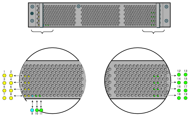
Each compute/memory blade installed in an IRU has a total of 19 LED indicators visible behind the perforated sheetmetal of the blade. Note that the heartbeat LEDs may not be available or functional on all versions of the compute blades:
At the bottom end (or left side) of the blade:
There are 8 amber heartbeat LEDs
One green 12V power good LED
One blue unit identifier (UI) LED
One green 3.3V auxiliary power LED
At the top end (or right side) of the blade:
There are four green NumaLink status LEDs
An auxiliary power good green LED
System power good green LED
Ethernet 0 green LED
Ethernet 1 green LED
If the blade is properly seated and the system is powered on and there is no LED activity showing on the blade, it must be replaced. Table 6-3 lists the blade's LED status information, Figure 6-1 shows the locations of the blade LEDs.
Table 6-3. Altix UV Blade LED Status Information
LED # | LED color | LED status information/message |
|---|---|---|
01 | Amber | CPU 0 heartbeat |
02 | Amber | CPU 1 heartbeat |
03 | Amber | CPU 0 heartbeat |
04 | Amber | CPU 1 heartbeat |
05 | Amber | CPU 0 heartbeat |
06 | Amber | CPU 1 heartbeat |
07 | Amber | CPU 0 heartbeat |
08 | Amber | CPU 1 heartbeat |
09 | Green | 12V power good to blade |
10 | Blue | Unit (blade) Identifier - blade is selected when lighted |
11 | Green | 3.3V auxiliary power is present on the blade |
12 | Green | NUMALink 0 status on blade |
13 | Green | Auxiliary power to blade is good |
14 | Green | NUMALink 01 status on blade |
15 | Green | System power to blade is good |
16 | Green | NUMALink 02 status on blade |
17 | Green | Ethernet 0 activity on blade |
18 | Green | NUMALink 03 status on blade |
19 | Green | Ethernet 1 activity on blade |
SGI Electronic Support provides system support and problem-solving services that function automatically, which helps resolve problems before they can affect system availability or develop into actual failures. SGI Electronic Support integrates several services so they work together to monitor your system, notify you if a problem exists, and search for solutions to problems.
Figure 6-2 shows the sequence of events that occurs if you use all of the SGI Electronic Support capabilities.
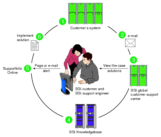
The sequence of events can be described as follows:
Embedded Support Partner (ESP) software monitors your system 24 hours a day.
When a specified system event is detected, ESP notifies SGI via e-mail (plain text or encrypted).
Applications that are running at SGI analyze the information, determine whether a support case should be opened, and open a case if necessary. You and SGI support engineers are contacted (via pager or e-mail) with the case ID and problem description.
SGI Knowledgebase searches thousands of tested solutions for possible fixes to the problem. Solutions that are located in SGI Knowledgebase are attached to the service case.
You and the SGI support engineers can view and manage the case by using Supportfolio Online as well as search for additional solutions or schedule maintenance.
Implement the solution.
Most of these actions occur automatically, and you may receive solutions to problems before they affect system availability. You also may be able to return your system to service sooner if it is out of service.
In addition to the event monitoring and problem reporting, SGI Electronic Support monitors both system configuration (to help with asset management) and system availability and performance (to help with capacity planning).
The following three components compose the integrated SGI Electronic Support system:
SGI Embedded Support Partner (ESP) is a set of tools and utilities that are embedded in the SGI Linux ProPack release. ESP can monitor a single system or group of systems for system events, software and hardware failures, availability, performance, and configuration changes, and then perform actions based on those events. ESP can detect system conditions that indicate potential problems, and then alert appropriate personnel by pager, console messages, or e-mail (plain text or encrypted). You also can configure ESP to notify an SGI call center about problems; ESP then sends e-mail to SGI with information about the event.
SGI Knowledgebase is a database of solutions to problems and answers to questions that can be searched by sophisticated knowledge management tools. You can log on to SGI Knowledgebase at any time to describe a problem or ask a question. Knowledgebase searches thousands of possible causes, problem descriptions, fixes, and how-to instructions for the solutions that best match your description or question.
Supportfolio Online is a customer support resource that includes the latest information about patch sets, bug reports, and software releases.
The complete SGI Electronic Support services are available to customers who have a valid SGI Warranty, FullCare, FullExpress, or Mission-Critical support contract. To purchase a support contract that allows you to use the complete SGI Electronic Support services, contact your SGI sales representative. For more information about the various support contracts, see the following Web page:
http://www.sgi.com/support/customerservice.html
For more information about SGI Electronic Support, see the following Web page: