The SGI Altix Integrated Compute Environment (ICE) systems are an integrated blade environment that can scale to thousands of nodes. The SGI Management Center for Altix ICE software enables you to provision, install, configure, and manage your system. This chapter provides an overview of the SGI Altix ICE system and covers the following topics:
This section provides a brief overview of the SGI Altix ICE system hardware and covers the following topics:
For detailed hardware descriptions, see the SGI Altix ICE 8200 Series System Hardware User's Guide or the SGI Altix ICE 8400 Series System Hardware User's Guide.
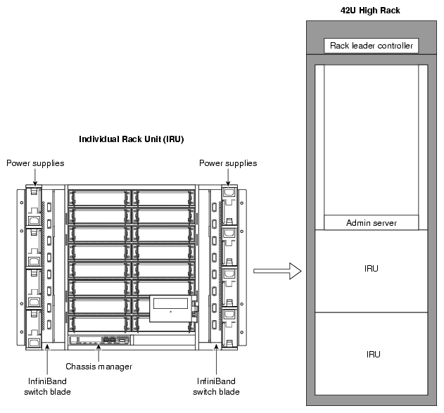
The SGI Altix ICE system is a blade-based, scalable, high density compute system. The basic building block is the individual rack unit (IRU). The IRU provides power, cooling, system control, and the network fabric for 16 compute blades.Figure 1-1 shows an Altix ICE 8200 series system. Four IRUs can reside in a custom designed 42U high rack.
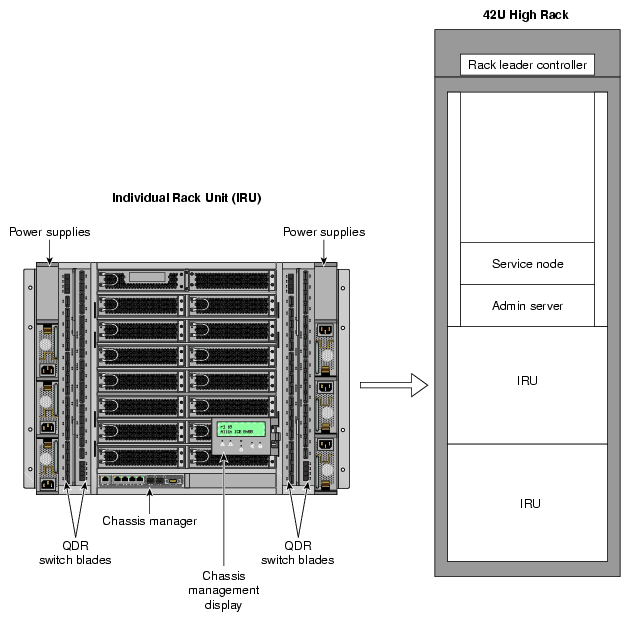
The Altix ICE 8400 series of computer systems are also based on an InfiniBand I/O fabric and may be equipped with either of two different single-wide blade types and quad-data rate (QDR) InfiniBand switch blades as shown in Figure 1-2.
For a detailed description of the Altix ICE 8400 series architecture, see the SGI Altix ICE 8400 Series System Hardware User's Guide .
This hardware overview section covers the following topics:
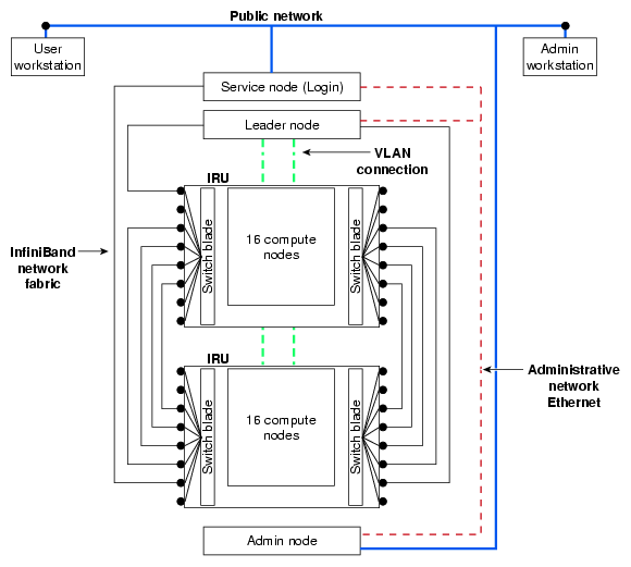
The SGI Altix ICE system uses an InfiniBand interconnect. Internal InfiniBand switch ASICs within the IRUs eliminate the need for external InfiniBand switches. InfiniBand backplanes built into the IRUs provide for fast communication between nodes and racks using relatively few InfiniBand cables.
The InfiniBand switch blade provides the interface between compute blades within the same chassis and also between compute blades in different IRUs. Fabric management software monitors and controls the InfiniBand fabric. SGI Altix ICE systems are usually configured with two separate InfiniBand fabrics. These fabrics (also sometimes called InfiniBand subnets) are referred to as "ib0" and "ib1" within this document.
For information on MPI and MPT, see the Message Passing Toolkit (MPT) User's Guide available on the SGI Technical Publications Library at http://docs.sgi.com . The ib1 fabric is reserved for storage related traffic. The default configuration for MPI is to use only the ib0 fabric. For more information on the InfiniBand fabric, see Chapter 4, “System Fabric Management”.
| Note: The “ ib0 fabric" is a convenient shorthand for "the fabric which is connected to the ib0 interface on most of the nodes”. Particularly in the case of storage service nodes, there may be several interfaces called ib0, ib1, and so on, all of which are connected to the same fabric (see “Storage Service Node ” and “NAS Configuration for Multiple IB Interfaces” in Chapter 2). The LX series only has one ib fabric, "ib0". Any references to "ib1" in this manual do not apply to LX systems. |
For performance reasons, it is often beneficial to use one fabric for message passing interface (MPI) traffic and the other for storage- related traffic. The default configuration for MPI is to use only the ib0 fabric and storage uses the ib1 fabric. For more information on the InfiniBand fabric, see Chapter 4, “System Fabric Management”.
Other configurations are possible, and may lead to better performance with specific workloads. For example, SGI's MPI library, the SGI Message Passing Toolkit (MPT), can be configured to use one, or both InfiniBand fabrics to optimize application performance. For information on MPI and MPT, see the Message Passing Toolkit (MPT) User's Guide available on the SGI Technical Publications Library at http://docs.sgi.com.
A Gigabit Ethernet connection network built into the backplane of the IRUs provides a control network isolated from application data. Transverse cables provide connection between IRUs and between racks. For more information on how the Gigabit Ethernet connection fabric is used, see “VLANs”.
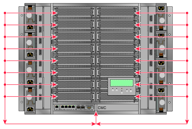
Each IRU has a one chassis management control (CMC) blade located directly below compute blade slot 0 as shown in Figure 1-1. This is the chassis manager that performs environmental control and monitoring of the IRU. The CMC controls master power to the compute blades under direction of the rack leader controller (leader node). The leader node can also query the CMC for monitored environmental data (temperatures, fan speeds, and so on) for the IRU.
Power control for each blade is handled by its Baseboard Management Controller (BMC), also under direction of the rack leader controller. Once the leader node has asked the CMC to enable master power, the leader node can then command each BMC to power up its associated blade. The leader node can also query each BMC to obtain some environmental and error log information about each blade.
| Note: Setting the circuit breakers on the power distribution units (PDUs) to the "On" position will apply power to the IRU and will start the chassis manager in each IRU. Note that the chassis manager in each IRU stays powered on as long as there is power coming into the unit. Turn off the PDU breaker switch that supplies voltage to the IRU if you want to remove all power from the unit. For detailed information about powering your system on or off, see the “Powering the System On and Off” section in chapter 1 of the SGI Altix ICE 8200 Series System Hardware User's Guide. |
The IRU provides data collected from compute nodes within the IRU to the leader node upon request.
The CMC and BMCs are powered by what is called "AUX POWER". This power supply is live any time the rack is plugged in and the main breakers are on. The CMC and BMCs are not able to be powered off under software control.
The compute blades have MAIN POWER which is controlled by the blade BMC. You can send a command to the BMC and have the main power to the associated blade turned on or off by that BMC.
The IRU has a MAIN POWER bus that feeds all of the blades. This main power bus can be turned on and off with a software command to the CMC. This "powering up of the IRU" turns on this main power, the fans in the IRU, and the power to the IB switches. The CMC, itself, is always powered on. This includes the Ethernet switch that is a part of the CMC.
| Note: Setting the circuit breakers on the power distribution units (PDUs) to the "On" position will apply power to the IRU and will start the chassis manager in each IRU. Note that the chassis manager in each IRU stays powered on as long as there is power coming into the unit. Turn off the PDU breaker switch that supplies voltage to the IRU if you want to remove all power from the unit. For detailed information about powering your system on or off, see the “Powering the System On and Off” section in chapter 1 of the SGI Altix ICE 8200 Series System Hardware User's Guide. |
The SGI Altix ICE system has a unique four-tier, hierarchical management framework as follows:
Unlike traditional, flat clusters, the SGI Altix ICE system does not have a head node. The head node is replaced by a hierarchy of nodes that enables system resources to scale as you add processors. This hierarchy is, as follows:
System admin controller (admin node)
Rack leader controller (leader node)
Service Nodes
Login
Batch
Gateway
Storage
The one system admin controller can provision and control multiple leader nodes in the cluster. It receives aggregated cluster management data from the rack leader controllers (leader nodes).
Each system rack has its own leader node. The leader node holds the boot images for the compute blades and aggregates cluster management data for the rack.
Ethernet traffic for managing the nodes in a rack is constrained within the rack by the leader node. Communication and control is distributed across the entire cluster, thereby preventing the admin node from becoming a communication bottleneck. Administrative tasks, such as booting the cluster, can be done in parallel rack-by-rack in a matter of seconds. For very large configurations, the access infrastructure can also be scaled by adding additional login and batch service nodes. It is the VLAN logical networks that help prevent network traffic bottlenecks.
| Note: Understanding the VLAN logical networks is critical to administering an SGI Altix ICE system. For more detailed information, see “VLANs” and “Network Interface Naming Conventions”. |
The rack leader controller (leader node) and system admin controller (admin node) are described in the section that follows (“System Nodes”).
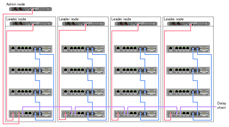
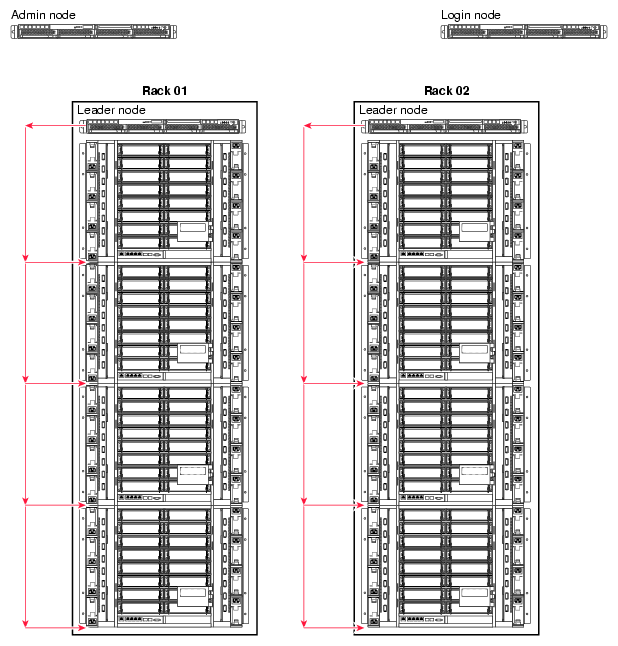
Figure 1-3 shows chassis manager cabling.
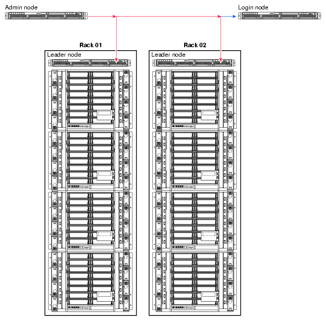
| Note: All nodes reside in the Altix ICE custom designed rack. Figure 1-3 and Figure 1-4 show how systems are cabled up prior to shipment. These figures are meant to give you a functional view of the Altix ICE hierarchical design. They are not meant as cabling diagrams. |
The chassis manager in each rack connects to the leader node in its own rack and also the chassis manager in the adjacent rack. The system admin controller (admin node) connects to one CMC in the rack. The rack leader controller (leader node) accesses the BMC on each compute node in the rack via VLAN running over a Gigabit Ethernet (GigE) connection (see Figure 1-8).
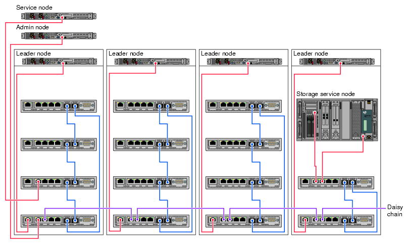
Figure 1-4 shows cabling for a service node and storage service node (NAS cube).
This section describes the system nodes that are part of SGI Altix ICE system and covers the following topics:
The system admin controller (admin node), is used by a system administrator to provision (install) and manage the SGI Altix ICE system using SGI Management Center (SMC) software. There is only one system admin controller per SGI Altix ICE system, as shown in Figure 1-3 and it cannot be combined with any other nodes. A GigE connection provides the network connection between the admin node, leader nodes, and service nodes. Communication to and from the CMC and compute blades from the leader nodes is controlled by VLANs to reduce network traffic bottlenecks in the system. The system admin controller is used to provision and manage the leader nodes, compute nodes and service nodes. It receives and holds aggregated management data from the leaders node. The admin node is an appliance node. It always runs software specified by SGI.
The rack leader controller (leader node) is used to manage the nodes in a single rack. The rack leader controller is provisioned and functioned by the system admin controller (admin node). There is one leader node per rack, as shown in Figure 1-3. A GigE connection provides the network connection to other leader nodes and to first IRU within its rack as shown in Figure 1-4 and Figure 1-5. An InfiniBand fabric connects it to the compute nodes within its rack and compute nodes in other racks. The leader node is an appliance node. It always runs software specified by SGI. The rack leader controller (leader node) does the following:
Runs software to manage the InfiniBand fabric in your Altix ICE system
Monitors and processes data from the IRUs within its rack
Monitors and processes data from compute nodes within its rack
Consolidates and forwards data from the IRUs and compute nodes within its rack to the admin node upon request
The leader node can contain multiple images for the compute nodes. “Customizing Software On Your SGI Altix ICE System” in Chapter 3 describes how you can clone and customize compute node images.
| Note: The following CMC description is the same as the information presented in “Basic System Building Blocks”. |
Each IRU has one chassis management control (CMC) blade located directly below compute blade slot 0 as shown in Figure 1-1. This is the chassis manager that performs environmental control and monitoring of the IRU. The CMC controls master power to the compute blades under direction of the rack leader controller (leader node).
| Note: Setting the circuit breakers on the power distribution units (PDUs) to the "On" position will apply power to the IRU and will start the chassis manager in each IRU. Note that the chassis manager in each IRU stays powered on as long as there is power coming into the unit. Turn off the PDU breaker switch that supplies voltage to the IRU if you want to remove all power from the unit. For detailed information about powering your system on or off, see the “Powering the System On and Off” section in chapter 1 of the SGI Altix ICE 8200 Series System Hardware User's Guide. |
The leader node can also query the CMC for monitored environmental data (temperatures, fan speeds, and so on) for the IRU. Power control for each blade is handled by the Baseboard Management Controller (BMC) also under direction of the rack leader controller. Once the leader node has asked the CMC to enable master power, the leader node can then command each BMC to power up its associated blade. The leader node can also query each BMC to obtain some environmental and error log information about each blade.
Figure 1-1 shows an IRU with 16 compute nodes. Users submit MPI jobs to run in parallel on the Altix ICE system compute nodes using a public network connection via the service node. The service node provides login services and a batch scheduling service, such as PBS Professional (PBSPro 9.x), as shown in Figure 1-5. The compute nodes are controlled and monitored by the leader node for their rack as shown in Figure 1-3. Compute nodes are booted and mount the shared, read-only portion of the root file system from the rack leader controller (leader node). The leader node provides the network connections to the compute nodes in the same rack and to leader nodes in other rack that then provide the network connections to the compute nodes in their racks. These network connections are via the InfiniBand fabric. The system admin controller does not communicate directly with the CMC or compute blades. Actions for the CMC and compute blades are sent to the appropriate leader node, which communicates to the appropriate CMC and compute blades. The compute nodes do not communicate directly to the CMC or admin nodes, or leader nodes outside their rack.
Generally, the CMC controller is not meant to be accessed directly by system administrators, however, in some situations you may need to access it to change a configuration using the CMC interface LCD panel. For example, in a single IRU system, you may need more Ethernet ports for service node or NAS cube connections. You can adjust the CMC to use the R58 jack or the L58 jack for this purpose (see Figure 1-6). For more information on these jacks, see “Gigabit Ethernet (GigE) and 10/100 Ethernet Connections”.
For information on the CMC interface LCD panel, see chapter 1 and chapter 6 of the SGI Altix ICE 8200 Series System Hardware User's Guide.
For more information about configuring compute nodes, see the following:
The individual rack unit (IRU) is one of the basic building blocks of the SGI Altix ICE system as shown in Figure 1-1. It is described in detail in “Basic System Building Blocks”.
The login service node allows users to login into the system to create, compile, and run applications. The login node is usually combined with batch and gateway service nodes for most configurations. The login service node is connected to the Altix ICE system via the InfiniBand fabric and GigE to the public customer network as shown in Figure 1-5. Additional login service nodes can be added as the total number of user logins grow.
The batch service node provides a batch scheduling service, such as PBS Professional. It is commonly combined with login and gateway service nodes for most configurations. It is connected to the Altix ICE system via the InfiniBand fabric and GigE to the public customer network. This node may be separated from gateway and/or login nodes to scale for large configurations or to run multiple batch schedules.
The gateway service node is the gateway from the InfiniBand fabric to services on the public network such as storage, lightweight directory access protocol (LDAP) services, and file transfer protocol (FTP). Typically, it is combined with the login/batch service node. This node may be separated from login and/or batch nodes to scale for large configurations.
The storage service node is a network-attached storage (NAS) appliance bundle that provides InfiniBand attached storage for the Altix ICE system. There can be multiple storage service nodes for larger Altix ICE system configurations. Figure 1-4 shows a service node and a storage service node (NAS cube).
For smaller Altix ICE systems, with less than one full rack of nodes (64 or less nodes), Network Attached Storage (NAS) is provided off an SGI XE250 system. It can also serve as a login or other support node using NFS. The XE250 is connected to the ICE system using InfiniBand (IB), and requires that Internet Protocol (IP) over IB be properly configured on the system to allow the Altix ICE nodes to be attach to the XE250 provided storage.
| Note: All nodes reside in the Altix ICE custom designed rack. Figure 1-3 and Figure 1-4 show how systems are cabled up prior to shipment. These figures are meant to give you a functional view of the Altix ICE hierarchical design. They are not meant as cabling diagrams. |
This section describes the Gigabit Ethernet (GigE) and 10/100 Ethernet connections and the InfiniBand fabric in an SGI Altix ICE system and covers the following topics:
This section describes the various network connections in the SGI Altix ICE system. Users access the system via a public network through services nodes such as the login node and the batch service node, as shown in Figure 1-5. A single service node can provide both login and batch services.
System administrators provision (install software) and manage the Altix ICE system via the logical VLAN network running over the GigE connection (see Figure 1-7, Figure 1-8, and Figure 1-9. The system admin controller (admin node) is on the house network (public network) and you access it directly.
The rack leader controller (leader node) provides boot and root filesystem images for the compute nodes in the same rack. The leader node is connected to blades in its rack via the GigE VLAN. It is connected to all service nodes and all other leader nodes via the InfiniBand fabric. Leader nodes have access to compute nodes in other racks via the leader node in that rack.
The gateway service node is the gateway from the InfiniBand fabric to services such as storage, lightweight directory access protocol (LDAP) services, file transfer protocol (FTP), and so on, on the public network. Typically, it is combined with the login/batch service node.
The system admin controller (admin node) and service nodes communicate with the leader node over a GigE fabric that has logically separate, virtual local area networks (VLANs). This GigE fabric is embedded in the backplane of each IRU. This GigE fabric electrically connects much of the Altix ICE system (see Figure 1-5).
Users access compute nodes strictly from the service nodes. Jobs are started on compute nodes using commands on the service node, such as, the OpenSSH client remote login program ssh (1), the submit a script to create a batch job qsub(1) command, or the pdsh(1) command (see “pdsh and pdcp Utilities” in Chapter 3) that enables the execution of any standard command on all Altix ICE system nodes.
You can use the interconnect verification tool (IVT) to verify that all the various 10/100 Ethernet, Gigabit Ethernet (GigE), and InfiniBand (IB) network links between the various system admin controllers (admin nodes), such as the admin or login node, the leader node, the compute nodes, the CMC and the BMC nodes are correctly connected and working properly after a system is installed or for maintenance purposes. For more information on IVT, see “Inventory Verification Tool” in Chapter 5.
The SGI Altix ICE 8200 system has several Ethernet networks that facilitate booting and managing the system. These networks are built onto the backplane of each IRU for connection to the compute blades and transverse cables between IRUs and between racks. Each compute blade has a Gigabit Ethernet (GigE) and 10/100 Ethernet connection to the backplane.
The GigE connection is an interface that is accessible to the operating system and the basic input/output (BIOS) running on the blade. It is the interface over which the BIOS uses the preboot execution environment (PXE) to PXE boot and it is known as eth0 on the configured node.
The 10/100 Ethernet interface is accessible to the management interface (BMC) built onto each compute blade. The operating system running on the blade cannot directly access this 10/100 interface. It belongs to the processor on the BMC. Likewise, the BMC cannot access the GigE interface.
Figure 1-6 shows a more detailed view of the Chassis manager.
The chassis management control (CMC) blade has two embedded Ethernet switches. One is a 24-port GigE switch and the other a 24-port 10/100 switch. The 10/100 switch is a sub-switch, hanging off one port, of the GigE switch.
The primary GigE interface from each of sixteen blades connects to the GigE switch and the sixteen blade BMCs connect to the 10/100 switch. The GigE connections also connect the service nodes, including the service storage nodes.
The GigE switches in each IRU are "stacked" using a special stacking connection between each IRU in a rack. This connection runs a special intra-switch protocol. All switches in a rack are ganged together to form one large 96 port switch. The connections from each CMC to another are labeled UP and DN as shown in Figure 1-6. The switches are stacked in a ring. The stacking ring is redundant and works in one direction, at a time, and if one direction breaks, it goes the other way around to ensure connectivity is preserved.
The processor on the CMC manages these switches effectively forming a large, intelligent Ethernet switch. A VLAN mechanism runs on top of this network to allow management control software to query port statistics and other port metrics including the attached peer's MAC address.
The CMC has five additional RJ45 connections on its front panel as shown in Figure 1-6. The function of these jacks is, as follows:
Local
This is a connection to the leader node at the top of the rack in which this CMC is located. Only one CMC (of the possible four) is connected to the leader node, as shown in Figure 1-3.
LL
Used to connect service nodes and service storage nodes. The RL jack in the far left CMC connects to the LL jack of the right adjacent CMC to create or grow the Ethernet network. Figure 1-3 shows this daisy chaining.
RL
Used to connect service nodes and service storage nodes. The RL jack in the far left CMC connects to the LL jack of the right adjacent CMC to create or grow the Ethernet network. Figure 1-3 shows this daisy chaining.
L58
This is a connection for the IEEE 1588 timing protocol from this CMC to the one immediately to the left. If this is the left-most rack, this jack is unconnected.
R58
This is a connection for the IEEE 1588 timing protocol from this CMC to the one immediately to the right. If this is the right-most rack, this jack is unconnected.
A NAS cube storage service node uses both the LL and RL jacks to connect to the Altix ICE system as shown in Figure 1-4.
For small, one IRU configurations, the L58 and R58 ports (see Figure 1-6) can be used to connect service nodes. This functionality can be enabled using the LCD panel of the CMC. It can also be done in the factory or by your SGI system support engineer (SSE).
Several virtual local area networks (VLANs) are used to isolate Ethernet traffic domains within the cluster. The physical Ethernet is a shared network that has a connection to every node in the cluster. The admin node, leader nodes, service nodes, compute nodes, CMCs, BMCs, all have a connection to the Ethernet. To isolate the broadcast domains and other traffic within the cluster, VLANs are used to partition it and are, as follows:
VLAN_1588
Includes all 1588_left and 1588_right connections, as well as an internal port to the CMC processor. This VLAN carries all of the IEEE 1588 timing traffic.
VLAN_HEAD
Includes all leader_local, leader_left , and leader_right connections. The VLAN_HEAD VLAN connects the admin node to all of the leader nodes (including the leader nodes' BMCs) and the service nodes.
VLAN_BMC
Includes all 10/100 sub-switches and the leader_local ports. The VLAN_BMC VLAN connects the leader nodes to all of the BMCs on the compute blades and to the CMCs within each IRU. See Figure 1-7.
VLAN_GBE
Includes all GigE blade ports and the leader_local port. The VLAN_GBE VLAN connects the leader nodes to the GigE interfaces of all the compute blades. See Figure 1-7.
VLAN_GBE and VLAN_BMC do not extend outside of any rack. Therefore, traffic on those VLANs stays local to each rack.
Only VLAN_HEAD extends rack to rack. It is the network used by the admin node to communicate to the leader node of each rack and to each service node.
The rack leader controllers (leader nodes) must run 802.1Q VLAN protocol over their downstream GigE connection to the CMC and the CMC LL port must also run 802.1Q. This is done for you when the rack leader controllers are installed from the system admin controller. For more information, see “Installing SMC for Altix ICE Admin Node Software ” in Chapter 2. Each VLAN should present itself as a separate, pseudo interface to the operating system kernel running on that leader node. VLAN _HEAD, VLAN_BMC, and VLAN_GBE must all transition the single Ethernet segment which connects the leader to the CMC in the rack below it.
The VLAN_GBE and VLAN_BMC networks connect the leader node in a given rack with the compute nodes (blades). In the case of VLAN_BMC, the network also connects the CMC with the compute blades and rack leader controller (leader node).
In an SGI Altix ICE system with just one IRU, the CMC's R58 and L58 ports are assigned to VLAN_HEAD by a field configurable setting. This provides two additional Ethernet ports that can be use to connect service nodes to your system. This is done in the factory or by your SGI system support engineer (SSE).
For information on the CMC interface LCD panel shown just about the CMC in Figure 1-7, see chapter 1 and chapter 6 of the SGI Altix ICE 8200 Series System Hardware User's Guide .
An InfiniBand fabric connects the service nodes, leader nodes, and compute nodes. It does not connect to the admin node or the CMCs. SGI Altix ICE systems usually have two separate network fabrics, ib0 and ib1.
| Note: The LX series only has one ib fabric, "ib0 ". Any references to "ib1" in what follows do not apply to LX systems |
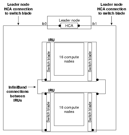
On SGI Altix ICE 8200 series systems, each rack leader controller (RLC), also called a leader node, has an InfiniBand host channel adapter (HCA) with two ports, each of which connects to a different fabric (see Figure 1-10).
Each IRU has internal InfiniBand switches which interconnect a fabric within the IRU (see Switch blade in Figure 1-10). A particular switch is part of only one fabric.
For a particular switch, each of 16 switch ports connects to one of the 16 compute nodes within the IRU. Some of the remaining switch ports are used for interconnections within the IRU, and the rest of the ports are exposed via connectors on the front of the IRU. InfiniBand cables between these connectors link the fabric between different IRUs, and one IRU in a rack is connected directly to its rack leader node (see Figure Figure 1-10).
On SGI Altix ICE 8400 series systems, rack leader controllers (leader nodes) will not always have InfiniBand fabric host channel adapters (HCA) depending on the system configuration. In some cases, one to two RLCs will have HCAs to run the OFED subnet manager. In other cases, this will be done on separate fabric management nodes, in this case no RLCs will have InfiniBand HCAs.
As described in “Networks”, you can think of an SGI Altix ICE system as having two distinct networks, the connections between the admin nodes, service nodes, and leader nodes, and the connections between the compute blades, CMCs, and the leader node within each rack. In general, these connections are made over one of the VLAN networks described in “VLANs”, but it is useful to be able to specify over which interface (VLAN) you are attempting to communicate. This section describes the naming strategy for logical type of interface being used. It covers the following topics:
Even though you may be communicating on different VLANs, you may in fact be communicating with the same physical network interface on the system. Naming the logical connections by function allows flexibility to change the number or type of the underlying physical networks. At the topmost level, the admin and service node nodes can communicate with the leader nodes over the VLAN_HEAD virtual network. The system component terms used in this section are described, as follows:
| Node | Refers to a building block within an SGI Altix ICE system (see “System Nodes”) | |
| Connection name | Denotes a resolvable name associated with an IP network | |
| Node name | Represents system-wide unique identifier for the building blocks of the SGI Altix ICE system. These IDs are partly not routable. See “Non-resolvable Names”. | |
| Hostname | Returns string of the hostname command. Is technically independent from the other names. |
System-wide unique names are node names and non-resolvable names.
X, Y, and Z in the following tables in this section are all integers.
Table 1-1 shows the VLAN_Head network connection names. See Figure 1-9.
Table 1-1. VLAN_HEAD Connections
Node | Connection Name |
|---|---|
Admin | admin |
Service | serviceX serviceX-bmc |
Leader | rXlead rXlead-bmc |
There is one admin node per system. You can have multiple service nodes labelled service0, service1, and so on. The BMC controllers for managed service nodes are accessible inside the network. BMCs for unmanaged service nodes are normally configured on the external network. For more information on managed service nodes, see “Installing Software on the Rack Leader Controllers and Service Nodes” in Chapter 2.
Table 1-2 shows the VLAN_GBE network connections.
Table 1-2. VLAN_GBE Network Connections.
Node | Connection Name | Node Name |
|---|---|---|
Leader | lead-eth | rXlead |
CMC | iYc | rXiYc |
Blade | iYnZ-eth | rXiYnZ |
The GBE VLAN is entirely internal to each rack (see Figure 1-7). The naming scheme is replicated between each rack, so the name i2n4-eth (identifying the VLAN_GBE interface on IRU 2, node 4) may match several different nodes, but only ever one in each rack. To identify a node uniquely, use the rXiYnZ syntax.
Blade rXiYnZ names are resolvable via DNS. They get the A record for the -ib0 address. The rXiYnZ-ib0 name is a CNAME to the rXiYnZ address. For example:
[root@sys-admin ~]# host r1i1n0 r1i1n0.ice.americas.sgi.com has address 10.148.0.20 |
[root@r1lead ~]# host r1i1n0 r1i1n0.ice.americas.sgi.com has address 10.148.0.20 |
Table 1-3 shows the VLAN_BMC network connections.
Table 1-3. VLAN_BMC Network Connections
Node | Connection Name | Node Name |
|---|---|---|
Leader | lead-bmc | rXlead |
CMC | iYc | rXiYc |
Blade | iYnZ-bmc | rXiYc |
The BMC VLAN is also local to each rack, in the same way as the GBE VLAN (see Figure 1-7).
Note that the interface lead-bmc on the leader node is not an interface to the BMC on the leader, but rather is an interface on the leader to the VLAN_BMC network in that leaders rack. Software running on other nodes in an Altix ICE system, outside of a given rack, cannot directly address the BMC's, or CMC, within said rack. Rather such requests much go through suitable application level software running on that rack's leader, when can in turn access the BMCs and CMC in its rack, via this lead-bmc interface to the racks VLAN_BMC network.
Connecting to the leader node's BMC is only possible from an admin node, service, or other leader node, when you should use rXlead-bmc .
The CMC does not have a BMC connection, but instead the VLAN_BMC connection is to the CMC's console interface.
Table 1-4 shows the VLAN_1588 network connections.
The 1588 VLAN carries the time synchronization traffic and connects CMCs in all the racks in the Altix ICE system. For this reason, the full rack-qualified name is needed to uniquely identify the target CMC.
Sometimes a rack, an IRU, or a CMC needs to be uniquely identified within the Altix ICE system. Table 1-5 shows the names that may be used for this, but there is no IP address associated with them. Therefore, DNS lookup will not succeed for these names. The names are used by certain Altix ICE management tools and are parsed internally to indicate which leader node to use in order to connect to the destination system.
Hostnames are distinct from the non-resolvable names and are shown in Table 1-6. In general, this is the name that you get by typing hostname at the command prompt on the system, and is used as a way of identifying the system to the user. Often, the command prompt is set up to contain the hostname. This is a benefit since with multiple windows open to different systems, it allows the user to avoid executing commands in the wrong window.
Node | Hostnames |
|---|---|
Admin | user assigned |
Leader | rXlead |
Blade | rXiYnZ |
CMC | rXiYc |
Service | user assigned (see Note below) |
| Note: By default, the host name for service nodes follow the convention serviceX. However, host names of service nodes or admin nodes can be changed using the cadmin command (see “cadmin: SMC for Altix ICE Administrative Interface ” in Chapter 3). |
The internal domain name service (DNS) has changed. The hostname
gets the A record and name -ib0
gets a CNAME alias. Additionally, if you changed the
hostname from the SMC for Altix ICE node name, there will be
CNAME alias for the
SMC for Altix ICE node name,
as well.
The zone looks similar to the following:
r1lead IN A 10.148.0.1 r1lead-ib0 IN CNAME r1lead.ice.mycompany.com. r1lead-ib1 IN A 10.149.0.1 r1i0n0 IN A 10.148.0.2 r1i0n0-ib0 IN CNAME r1i0n0.ice.mycompany.com. r1i0n0-ib1 IN A 10.149.0.2 r1i0n1 IN A 10.148.0.3 r1i0n1-ib0 IN CNAME r1i0n1.ice.mycompany.com. r1i0n1-ib1 IN A 10.149.0.3 [...] |
In the example above, the node/hostname gets the A record. The -ib0 name is a CNAME alias to the node/hostname. ib1 remains same as previous releases.
The InfiniBand fabric is connected to service nodes, rack leader controllers (leader nodes), and compute nodes, but not to the system admin controller (admin node) or CMCs. Table 1-7 shows InfiniBand names. There are two IB connections to each of the nodes that use it. Since IB is not local to each rack, you must use the fully-qualified, system-unique node name when specifying a destination interface. It may be necessary to alias the rXiYnZ names (currently non-resolvable) to rXiYnZ-ib0 if this is needed by MPI. Technically, rXiYnZ from a leader node points at the VLAN_GBE interface for the compute blade while from a service or compute blade, rXiYnZ points to the ib0 interface.
In DNS, the rXiYnZ name is the A record, with the -ib0 address, rXiYnZ-ib0, the CNAME alias to the rXiYnZ A record. The same applies to service nodes (see “Hostnames”).
If you change the node name, the new name is the A record, with the -ib0 address,newname-ib0 , the CNAME alias to the new name A record. The old name is a CNAME alias to the new name A record.
Node | Connection Name | Node Name |
|---|---|---|
Service | serviceX-ib0 serviceX-ib1 | serviceX |
Leader | rXlead-ib0 rXlead-ib1 | rXlead |
Blade | rXiYnZ-ib0 rXiYnZ-ib1 | rXiYnZ |
| Note: The host name of a service node can be changed from the default. |
